Base Plate and Anchor Bolt / Shear Key Connection
In this section you will find the sample calculation reports of Base Plate and Anchor
Bolt / Shear Key Connection generated by this program.
Load Input for Base Plate and Anchor Bolt Shear Key Connection
Below is the detail explanation on base plate & anchor bolt design load inputs
|
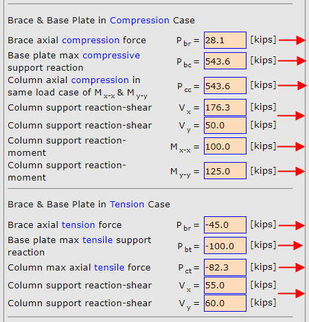
Load case when base plate , column and ver brace are in compression
|
|
Pc1 , max axial compression force in ver brace when there is ver brace |
|
Pc2 , max compresssion force on base plate. When there is ver brace, Pc2 is the resultant of ver brace Pc1 above and column axial Pc3 below
|
Pc3 , max axial compresssion force in column. It should be taken from the same load case as max Mx-x and My-y inputs below as it will be
used
to offset tensile force caused by moment in column-to-base plate weld design
|
|
max shear force on base plate in X and Y direction
|
|
max column base moment about X-X axis |
|
max column base moment about Y-Y axis |
|
Load case when base plate , column and ver brace are in tension
Set all values to zero if there is no tension
case |
|
Pt1 , max axial tension force in ver brace when there is ver brace |
|
Pt2 , max tension force on base plate. When there is ver brace, Pt2 is the resultant of ver brace Pt1 above and column axial Pt3 below
|
|
Pt3 , max column axial tension force. It will be used in column-to-base plate weld design
|
|
max shear force on base plate in X and Y direction
|
|
|