Skip Navigation LinksHome > Connection Library > Slip Critical Bolt Connection and Slotted Bolt Hole
Skip Navigation Links.
Collapse HomeHome
Steel Connection Design Manual
Everything About Licensing
Buy a License / How to Login
Change Login Name and Password
Quick Start - New User
CivilBay Engineering Services
Collapse Connection LibraryConnection Library
Moment Connection Type
Moment Connection-Extended End Plate Type
Moment Connection - Tutorial
Shear Connection
Shear Connection - Tutorial
Brace Connection Type
Brace Hor Member Connection Type
Brace Hor Strut Connection Type
Ver Brace Connection - Tutorial
Hor Brace Connection - Tutorial
Splice Connection
Splice Connection Type
Splice Connection - Tutorial
Base Plate and Anchor Bolt Connection
Hollow Section Steel Connection
Slip Critical Bolt Connection and Slotted Bolt Hole
Collapse Concrete Anchorage DesignConcrete Anchorage Design
Conc Anchorage Design Manual
Base Plate Anchor Bolt Pattern
Anchor Bolt Design Seismic Provisions - ACI 318-19
Anchor Bolt Design Seismic Provisions - CSA A23.3-19
Vertical Vessel Anchorage Design - Skirt Support and Leg Support
Collapse Sample CalculationSample Calculation
Collapse Moment ConnectionMoment Connection
MC-4 Bolt Extend End Plate
MC at Column Top - Column Siffener Plate
MC at Both Sides of Column - Column Siffener and Doubler Plate
MC-2 Bolts Top Flush End Plate
MC-12 Bolts Extend End Plate MRE 1/3-4W/2W
MC-Flange Plate to Column Flange
MC-Flange Plate to Column Web
Collapse Moment Connection-SeismicMoment Connection-Seismic
OMF MC-4 Bolt 4E Extend End Plate
OMF MC-8 Bolt 8ES Extend End Plate
SMF BFP Bolted Flange Plate
Collapse Shear ConnectionShear Connection
End Plate-Beam to Column Flange
End Plate-Beam to Column Web
End Plate-Beam to Girder
End Plate-Beam to Girder with Stiffened Coped Beam
Clip Angle-Beam to Column Flange
Clip Angle-Beam to Column Web
Clip Angle-Beam to Girder
Clip Angle-Beam to Girder with Stiffened Coped Beam
Shear Tab-Beam to Column Flange
Shear Tab-Beam to Column Web
Shear Tab-Beam to Girder
Shear Tab-Beam to Girder with Stiffened Coped Beam
Collapse Vertical Brace ConnectionVertical Brace Connection
W Shape Brace to Column Web
W Shape Brace to Column Flange
Collapse Vertical Brace - SeismicVertical Brace - Seismic
SCBF HSS Ver Brace
SCBF HSS Chevron Brace-Top
SCBF HSS Chevron Brace-Bottom
Collapse Horizontal Brace ConnectionHorizontal Brace Connection
Horizontal Brace-End Plate
Horizontal Brace-Wrap Around Gusset Plate-Clip Angle
Horizontal Brace-Wrap Around Gusset Plate-Shear Tab
Collapse Chevron Brace ConnectionChevron Brace Connection
Chevron Brace
Collapse Knee Brace ConnectionKnee Brace Connection
Knee Brace
Collapse Base Plate Ver Brace ConnectionBase Plate Ver Brace Connection
Base Plate Ver Brace-Column Flange
Base Plate Ver Brace-Column Web
Collapse Splice ConnectionSplice Connection
Splice-Exterior Flange Plate
Splice-Exterior/Interior Flange Plate
Splice-Top & Bottom Extended End Plate
Splice-Top Flushed & Bottom Extended End Plate
Slip Critical Bolt Connection and Slotted Bolt Hole
 
User can view this tutorial  video on how to design slip critical bolt connection
 
1.  How to Design Slip Critical Bolt Connection
2.  Bolt Connection - Types of Bolt Hole
3.  Slip Critical Bolt Connection Code Provision
4.  Slip Critical Bolt Connection FAQs
5.  Slotted Hole Bolt Hole Size from AISC Design Manual


1. How to Design Slip Critical Bolt Connection         Back to Top
 
For bolt connection, user can go to bolt setup dialog box and select Consider slip critical Yes/No as shown below to initiate bolt sclip critical check


2. Bolt Connection - Types of Bolt Hole         Back to Top
 
Below is the type of bolt hole
STD = standard hole
OVS = oversized hole
SSLT = short-slotted hole oriented transverse to the line of force
SSLP = short-slotted hole oriented parallel to the line of force
LSLP = long-slotted hole oriented parallel to the line of force
LSLT = long-slotted hole oriented transverse to the line of force


3. Slip Critical Bolt Connection Code Provision         Back to Top
 
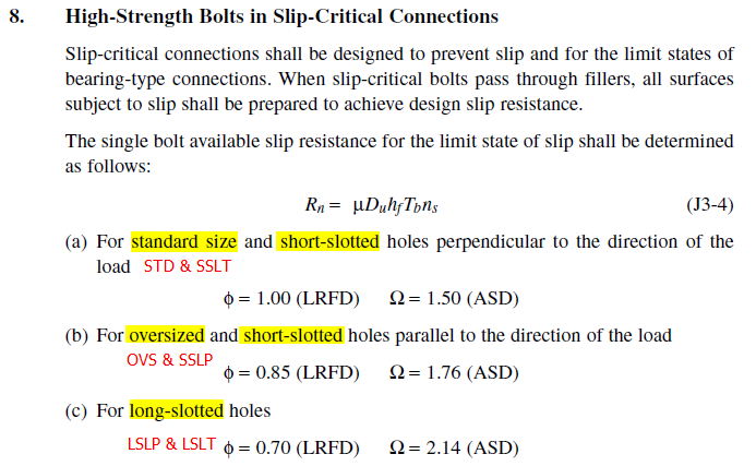
Below is the AISC Manual code provisions to deal with different bolt hole types


4. Slip Critical Bolt Connection FAQs         Back to Top
 
>> Can you verify that SSLT holes can be used with bearing type bolts?
When user selects Consider slip critical = Yes , no matter what type of bolt hole is selected, the program will check both bolt bearing and bolt slip critical in
the bolt shear capacity check.
 
>> I went into the SC bolt tab, set the slots in the plate then clicked "no" for SC bolts, is that correct?
If user needs slip critical check, user must select Consider slip critical = Yes
Whether you need slip critical check or not, it all depends on the load of concern and slotted hole direction 
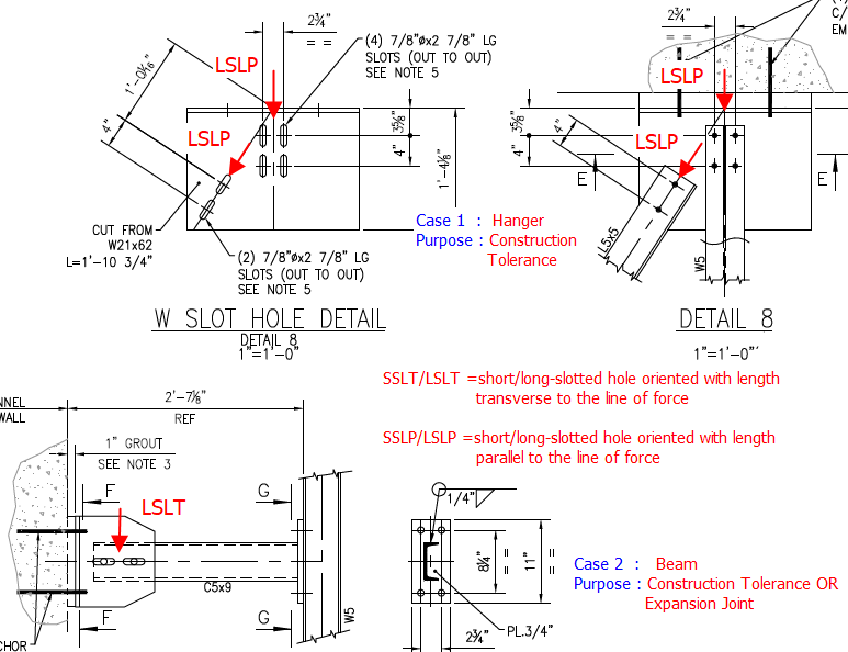
in your connection design. Look at sketch below
In Case 1, it is slotled hole connection in a hanger case, purpose of slotted hole is to account for construction tolerance when steel connecting to concrete.
In this case you need slip critical check so you must select Consider slip critical = Yes
In Case 2, it is slotled hole for a beam case, purpose of slotted hole can be 1) for construction tolerance OR 2) for expansion joint
In case 2 the load of concern is apparently the vertical shear load, not the horizontal beam axial load. In this case user can choose LSLT/SSLT or even STD
bolt hole as only vertical shear bolt bearing check is a concern. In the horizontal slotted hole direction, not only slip critical friction resistance is not a concern,
user may further expect it to move freely for expansion joint case, so user doesn't need slip critical check at all in this case, and user can choose STD hole instead
of slotted hole in this connection design.


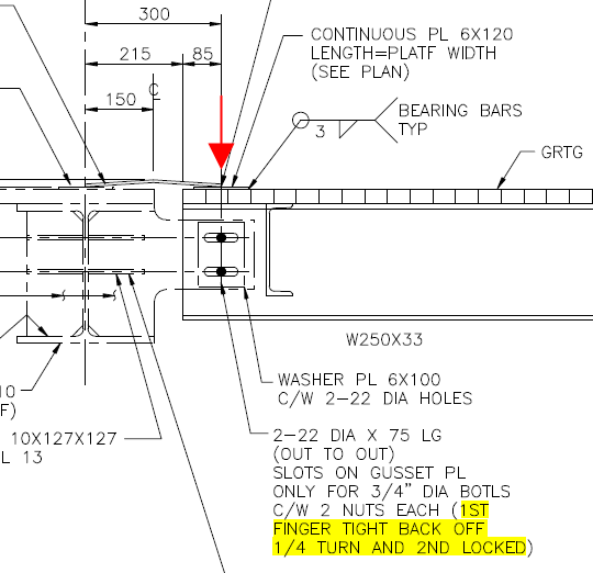
Look at sketch below, in the beam end slotted hole case, when you see the yellow highlighted note 1ST NUT FINGER TIGHT THEN BEACK OFF 1/4 TURN ...
That indicates that the slotted hole here is for expansion joint purpose, the bolts are allowed to move freely in horizontal direction like a roller, so the slip
critical check is NOT required in this case because
1) The load of cencern is vertical load. In horizontal direction instead of slip critical friction resistance, we want to release it
2) In vertical direction it's not slotted hole. Bolt bearing is checked in vertical direction so slip critical is not required.
For this case, user can select Consider slip critical = No and use STD hole in connection design although in detail it's a slotted hole connection.


>> I have not been able to verify if slots are accounted for in the calc's or not.
If Consider slip critical = Yes is selected, the program will do additional bolt slip critical check on top of bolt bearing check for shear
If Consider slip critical = No is selected, the program will only do the bolt bearing check for shear  

>> Your output does not show that for slotted hole the enlarged hole size is considered in plate Block Shear check plate net area Ant and Anv calculation
It's correct that the enlarged slotted bolt hole or oversized bolt hole is not considered in Plate Block Shear plate net area Ant and Anv calculation.
In the Plate Block Shear calculation, all bolt holes are assumed to be standard bolt holes.
When there are slotted or oversized bolt holes, User can select the bolt hole type as SSLT/SSLP or LSLT/LSLP or OVS from Bolt Hole Type pulldown in the bolt
setup dialog box. This will generate an accurate calculation for Bolt Slip Critical check.
For Plate Block Shear check, user can just simply increase the bolt edge distance manually, in the slotted hole direction only, after finishing the calculation.
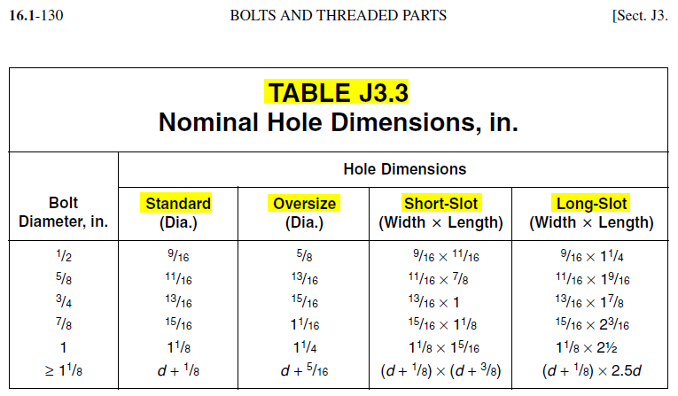
For example, the 1" dia bolt STD hole dh =1-1/8", long slotted hole out-out length=2-1/2", one side extra length=(2.5 - 1.125) /2 =0.688", we round it up to 0.75"
Assume bolt edge distance is 1.5", user can increase the bolt edge distance to 1.5" + 0.75" = 2.25", in long slotted hole direction only as final bolt edge distance.
This manual increase of bolt edge distance will make sure that the Plate Block Shear check is now accurate.  


5. Slotted Hole Bolt Hole Size from AISC Design Manualal         Back to Top
 
Below is the bolt slotted hole size from AISC Design Manual Table J3.3