Seismic Design Category SDC
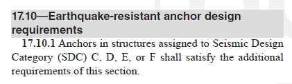
ACI 318-19 17.10.1
Anchors in structures assigned to Seismic Design Category (SDC) C, D, E, or F shall
satisfy the additional requirements of this section.
ACI 318-19 17.10.1
How to find out your structure's Seismic Design Category SDC
1) Refer to ASCE 7-16 page 2 Table 1.3-1 to find out the
Risk
Category of your structure based on your structure's type and usage.
2) Refer to ASCE 7-16 page 84 Section 11.4.5 to find out the design spectral response
acceleration parameters
SDS and
SD1 based on your structure's location
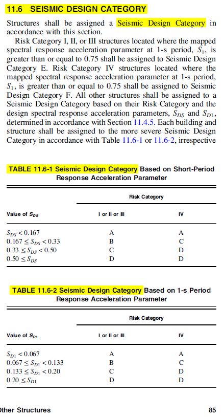
3) Refer to ASCE 7-16 page 85 Section 11.6 Table 11.6-1 and 11.6-2 to find out the
SDC for your structure.
ASCE 7-16 page 85 Section 11.6
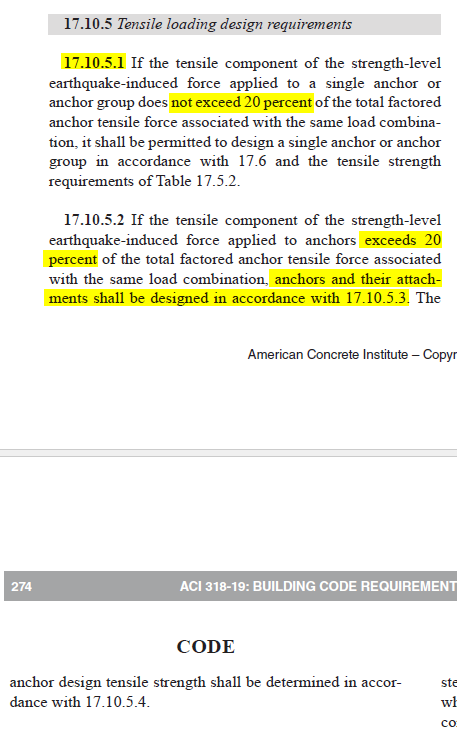
ACI 318-19 17.10.5.1
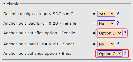
This input is required when seismic SDC>=C. User can ignore this input when seismic
SDC=A or B
Select
Yes when E <= 0.2U
Select
No when E > 0.2U
E - Seismic component in the total factored
tensile
load N
u user input above
U - Total factored
tensile load N
u user
input above
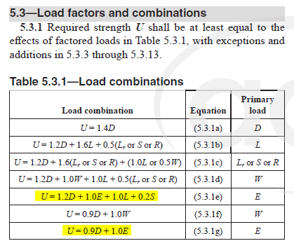
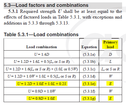
Below are load combinations from ACI 318-19 5.3.1 by which user uses to get
the total factored
tensile load N
u for
anchor bolt design.
|
ACI 318-19 5.3.1
|
ACI 318-19 17.10.5.1
|
|
|
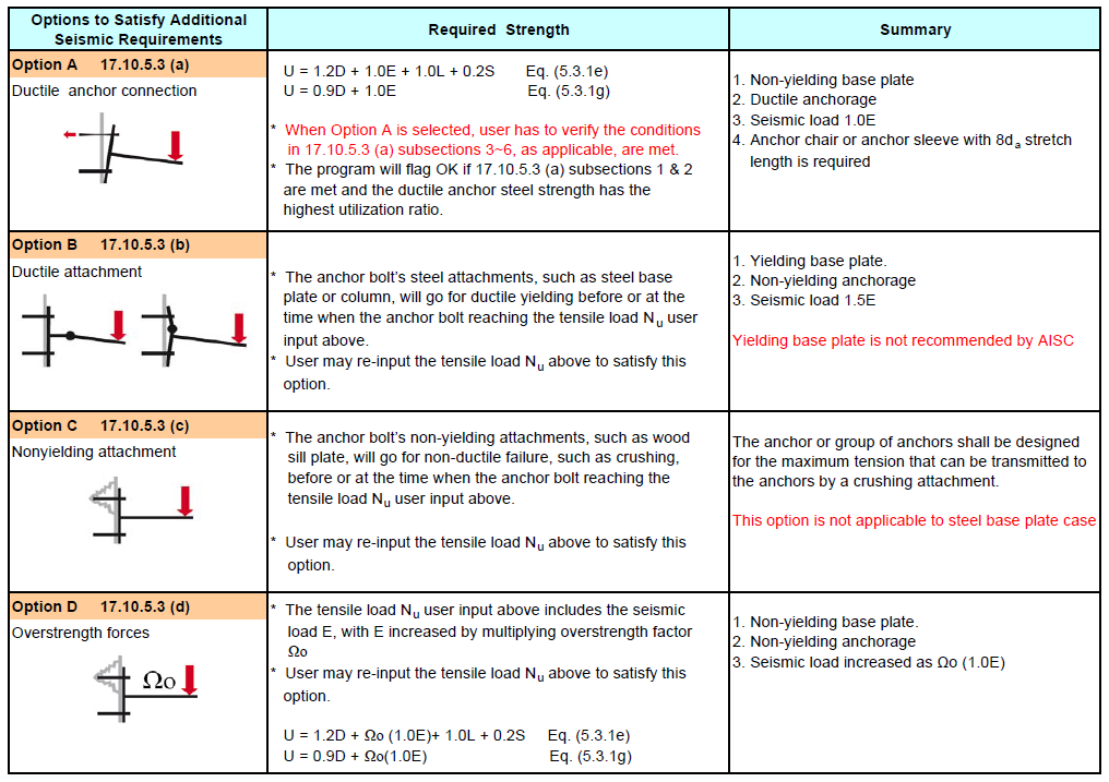
Tensile - Options to Satisfy Additional Seismic Requirements
ACI 318-19 17.10.5.3 (a) ~ (d)
This input is required when
Seismic SDC >= C (17.10.1)
AND
Tensile E > 0.2U (17.10.5.2)
User can ignore this input when
Seismic
SDC < C (17.10.1)
OR
Tensile E <= 0.2U (17.10.5.1)
If user selects
Option D below, check this
help file
for more details on Ω
o factor
If user selects
Option D above, check this
help file
for more details on Ω
o factor
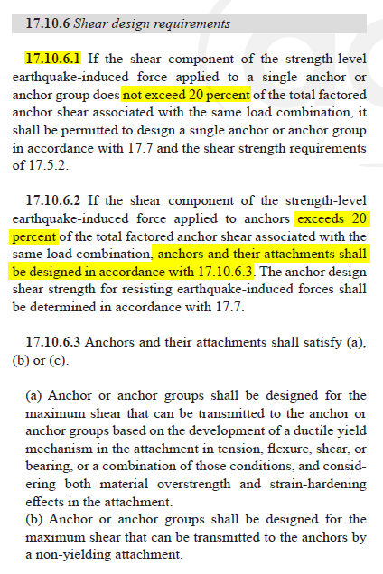
Anchor Bolt Shear Load Seismic Component E<=0.2U
ACI 318-19 17.10.6.1
This input is required when seismic SDC>=C
User can ignore this input when seismic SDC=A or B
Select
Yes when E <= 0.2U
Select
No when E > 0.2U
E - Seismic component in the total factored
shear
load V
u user input above
U - Total factored
shear load V
u user
input above
Below are load combinations from ACI 318-19 5.3.1 by which user uses to get
the total factored
shear load V
u for
anchor bolt design.
|
ACI 318-19 5.3.1
|
ACI 318-19 17.10.6.1
|
|
|
|
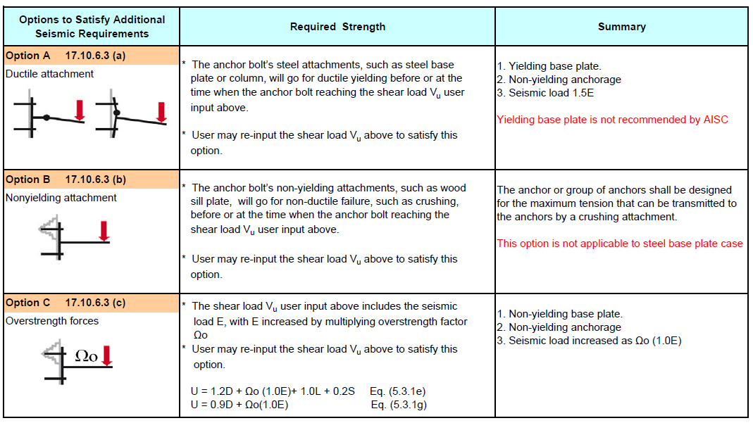
Shear - Options to Satisfy Additional Seismic Requirements
ACI 318-19 17.10.6.3 (a) ~ (c)
This input is required
when
Seismic SDC >= C (17.10.1)
AND
Shear E > 0.2U (17.10.6.2)
User can ignore this input when
Seismic SDC <
C (17.10.1)
OR
Shear E <= 0.2U (17.10.6.1)
If user selects
Option C below,
check this
help file
for more details on Ω
o factor
If user selects
Option C above, check this
help file
for more details on Ω
o factor
For anchor bolt design when SDC>=C and E>0.2U, anchor bolt design shall satisfy
For tension , one of the 4 options in ACI 318-19 17.10.5.3 (a)~(d) or
For shear , one of the 3 options in ACI 318-19 17.10.6.3 (a)~(c)
For steel structure, the practical options engineers normally choose are
For tension , ACI 318-19 17.10.5.3 (a)~(d) , use option (a) or (d) , select
option (a) by adopting anchor chair and
using anchor tensile load with Ω
o=1.0 is the most practical
and preferable option
For shear , ACI 318-19 17.10.6.3 (a)~(c) , use option (c)
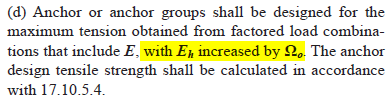
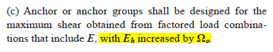
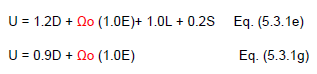
If for tension 17.10.5.3 (d) is chosen or for shear shear 17.10.6.3 (c) is chosen,
user need to increase the seismic
load E by multiplying overstrength factor Ωo
|
ACI 318-19 17.10.5.3 Option (d)
|
ACI 318-19 17.10.6.3 Option (c)
|
|
|
Refer to section right below on how to get the Ω
o values based on the type of
your steel frame.
When the steel frame engineer proceeds with the steel frame seismic design, the enginner
first needs to figure out
what seismic design parameters shall be used.
Below are some parameters which are related to seismic anchorage design
SDC Seismic Design Category
R Response Modification Coefficient
Ω0 Overstrength Factor
It depends on what category
user's steel frame can be classified into, user needs to select one from
multiple tables in
ASCE 7-16 to get the correct
R and
Ω0 factor for seismic anchorage
design.
ASCE 7-16 Table 12.2-1 for residential/commercial building structures, such as highrise
office and condo buildings
ASCE 7-16 Table 15.4-1 for industrial structures - nonbuilding
structures
similar to buildings, such as mill buildings
ASCE 7-16 Table 15.4-2 for
industrial structures - nonbuilding structures
not similar to buildings, such as
anchorage for tank, vessel, silo etc
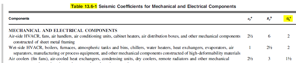
ASCE 7-16 Table 13.6-1 for Mechanical and Electrical components
Table 12.2-1 for residential/commercial building structures,
such as highrise office and condo buildings
Refer to ASCE 7-16 Table 12.2-1, in summary, the Ωo values for steel frames are
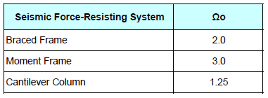
ASCE 7-16 Table 12.2-1
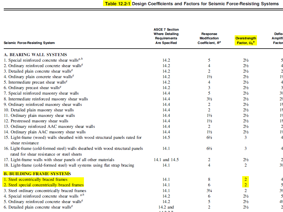
Table 15.4-1 for industrial structures - nonbuilding
structures
similar to buildings, such as mill buildings
The author is on industrial design background. Most industrial steel structures,
such as mill buildings and piperack structures, are in this category.
ASCE 7-16 Table 15.4-1
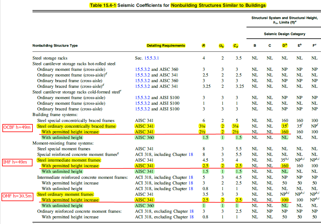
From
above Table 15.4-1
Ωo =2.0 for both OCBF/OMF/IMF highlighted as yellow
Ωo =1.0 for all NL=No Limit height option highlighted as green
Table 15.4-2 for
industrial structures - nonbuilding structures
not similar to buildings, such as
anchorage for tank, vessel, silo etc
The author is on industrial design background. Most industrial
equipment supports,
such as vessel and tank support, are in this category.
ASCE 7-16 Table 15.4-2
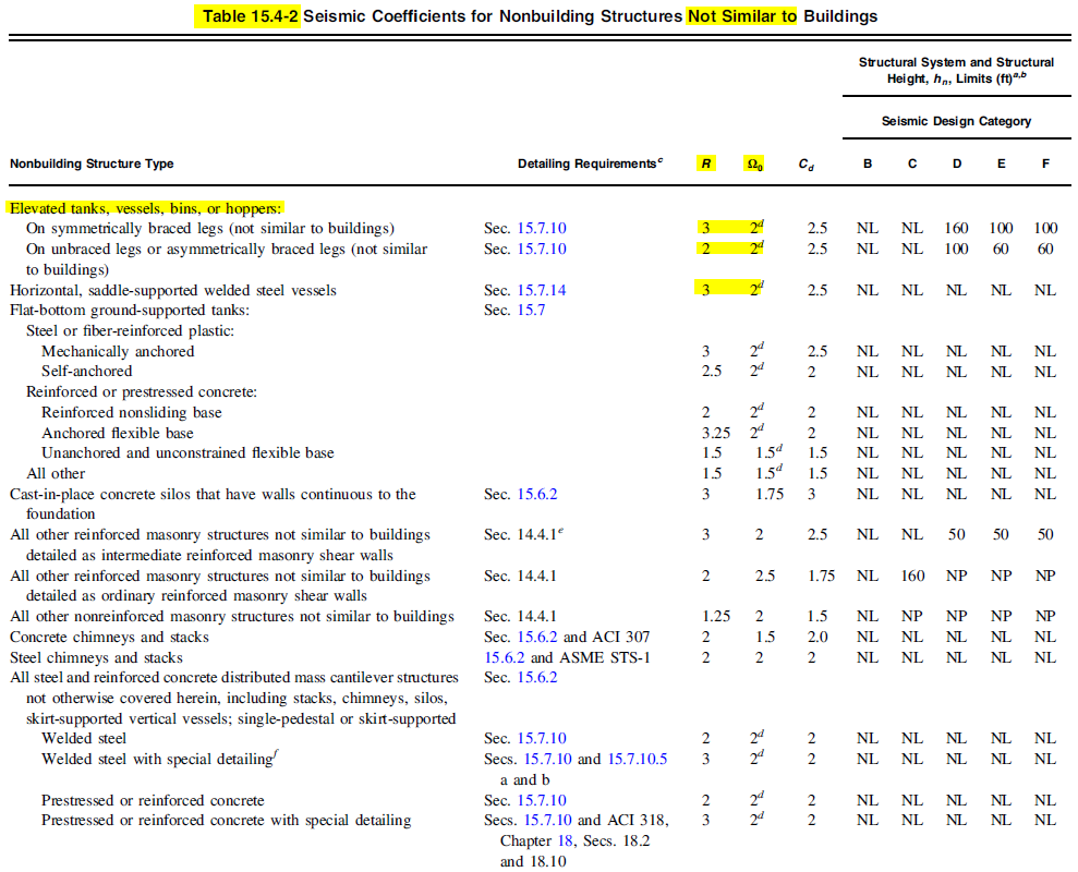
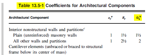
Table 13.6-1 Seismic Coefficients for Mechanical and Electrical
Components
This table is for Mechanical or Architectural components attached to building
ASCE 7-16 Table 13.5-1
& 13.6-1
How Can I Incorporate This Seismic Design Overstrength
Factor Ωo for My Anchor Bolt Designgn
|
Back to Top
|
1. Once you get the overstrength Factor Ωo , you can incorporate this Ωo factor
into the seismic component in the load combinations as shown
below in red.
2. In Civilbay anchorage program load input fields, input the tensile N
u
and shear V
u loads getting from load combinations where the E component
was increased by multiplying overstrength factor Ωo.
|
ACI 318-19 5.3.1
|
|
|
3. Select Tensile = Option D and Shear = Option C as shown below in Civilbay anchorage
design program.