|
CivilBay AISC Steel Connection Design Manual
|
|
|
|
Quick Start
|
|
|
|
|
|
|
|
How to Use
|
|
|
|
|
|
|
|
Steel Connection Design Tips
|
|
|
|
|
|
|
1. Why this program is the best steel connection design
program ?
|
Back to Top
|
Civilbay steel connection design program is one of the most comprehensive steel
connection design software based on AISC 360-16 and
AISC 360-10 code, CSA S16-14 code, and all AISC Steel Design Guides.
1. It's a pure AISC solution which covers 90~95% of steel connection design in most
projects, with specific strength on brace connection design
including vertical brace, horizontal brace, chevron brace, knee
brace, ver. brace to base plate , and wrap around gusset plate design in horizontal
brace design.
2. It provides detailed sketches and textbook style step by step calculation showing
formulas and parameters. In every step it shows the design
code reference source for the user to trace how the result is
derived so that the user has full control on the calculation.
2. Where can I buy a license and how much is the cost ?
|
Back to Top
|
User can click on this link
Buy Now
to buy a license online.
When user navigate through the
Buy Now
link , user will find license pricing info.
3. Which web browser is the best one to run this program
?
|
Back to Top
|
Use Google Chrome as your web browser
4. Where can I find the online tutorial video ?
|
Back to Top
|
5. How to start the program ?
|
Back to Top
|
To run the concrete anchorage design program online, visit
Start Program
6. Quick introduction on the user interface
|
Back to Top
|
User can view
Youtube video on this Tutorial
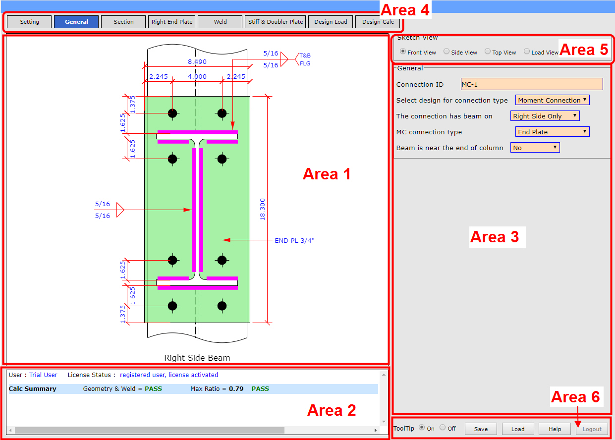
See screenshot below for the user interface input and display areas
Area-1 : sketch area, sketch is shown in this area. Users can
change different views of same connection by clicking on radio button in Area-5
Area-2 : status area, showing license status and calculation
result summary in this area Area-3 : input area,
users key in inputs in this area, by clicking on different tabs in Area-4, the input
fields will change to serve different part
of inputs for the connection Area-4 : input tabs, clicking
on different tabs in this area it will change the input contents shown in Area-3
Area-5 : sketch view tabs, clicking on different tabs in this
area it will change the sketch view shown in Area-1
Area-6 : file/login area, user can save/load input file, update
input and login/logout in this area
7. How to login as a licensed user ?
|
Back to Top
|
User can view
Youtube video on this Tutorial
For licensed user, you will get an email from me after you pruchased the license.
That email will give you login user name and password.
Key in your login user name and password as shown below
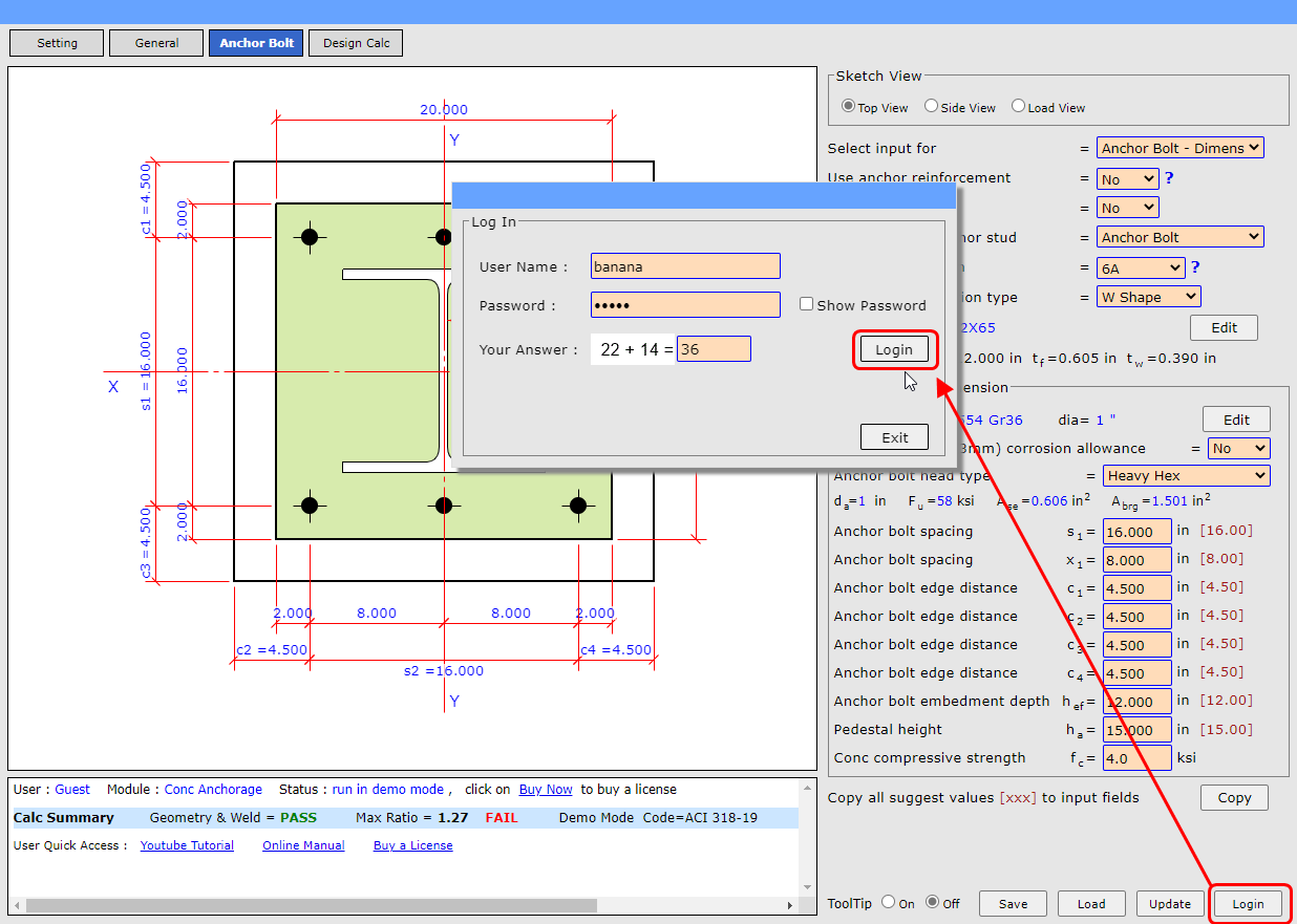
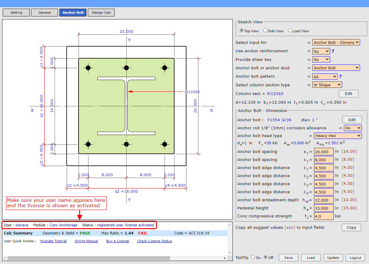
After login please verify that your user name appears on the status area and the
license is shown as activated.
8. How to change my login user name and password ?
|
Back to Top
|
Click on this link
Change Login
to change login user name and password.
9. How to navigate between different design modules ?
|
Back to Top
|
User can view
Youtube video on this Tutorial
There are
Steel Connection and
Concrete Anchorage two design modules.
User has purchased
Steel Connection license , but
Concrete Anchorage design module needs separate
license. We encourage
Steel Connection
user to have a free trila on
Concrete Anchorage
module.
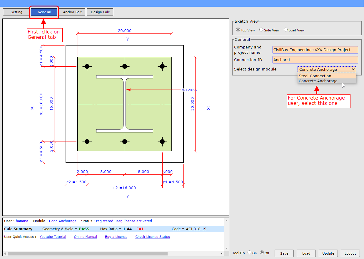
For
Steel Connection user, follow two setps below
to select
Steel Connection design module.
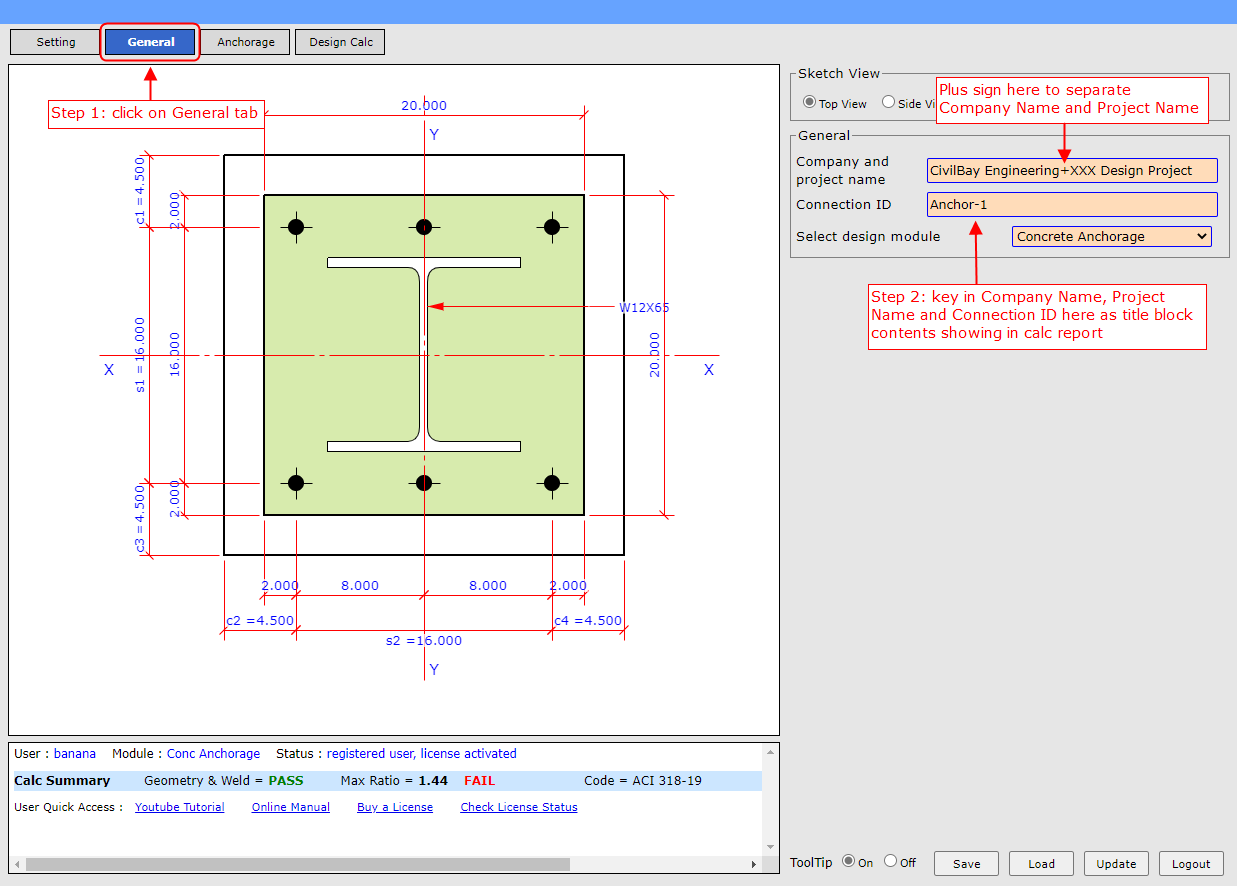
Step 1 : Click on
General tab as shown below
Step 2 : Select
Steel Connection design module from
the pull down as shown below
10. How to choose design code and set up design unit ?
|
Back to Top
|
User can view
Youtube video on this Tutorial
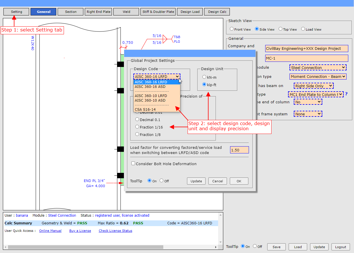
Step 1 : Click on
Setting tab as shown below
Step 2 : On the pop-up dialog box, select Design Code, Design Unit and Display Precision
Design Code : There are three design codes available as shown below
Design Unit : It will set the Imperial or Metric unit for input
and calculation presentation
User can design ACI 318-19 Imperial code using metric design unit
User can also design A23.3-19 Metric code using imperial design unit
Display Precision : It sets how the number is presented on the sketch, for
example half an inch display as 0.500 or 1/2";
This setting applies to sketch presentation only and does not
apply to calculation report presentation
11. Load input and load sign convention
|
Back to Top
|
User can view
Youtube video on this Tutorial
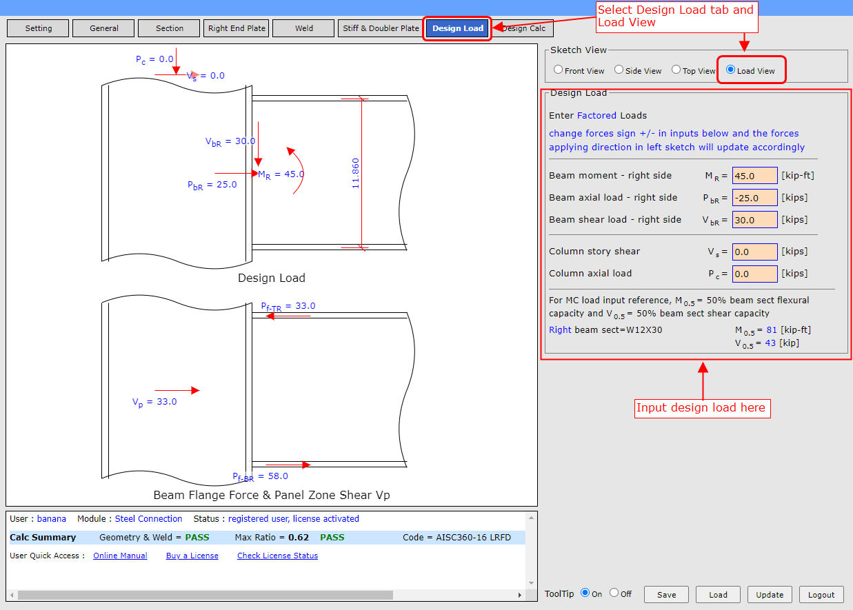
For axial load input, negative value denotes tensile load and positive value denotes
compression load
12. User input and update
|
Back to Top
|
User can view
Youtube video on this Tutorial
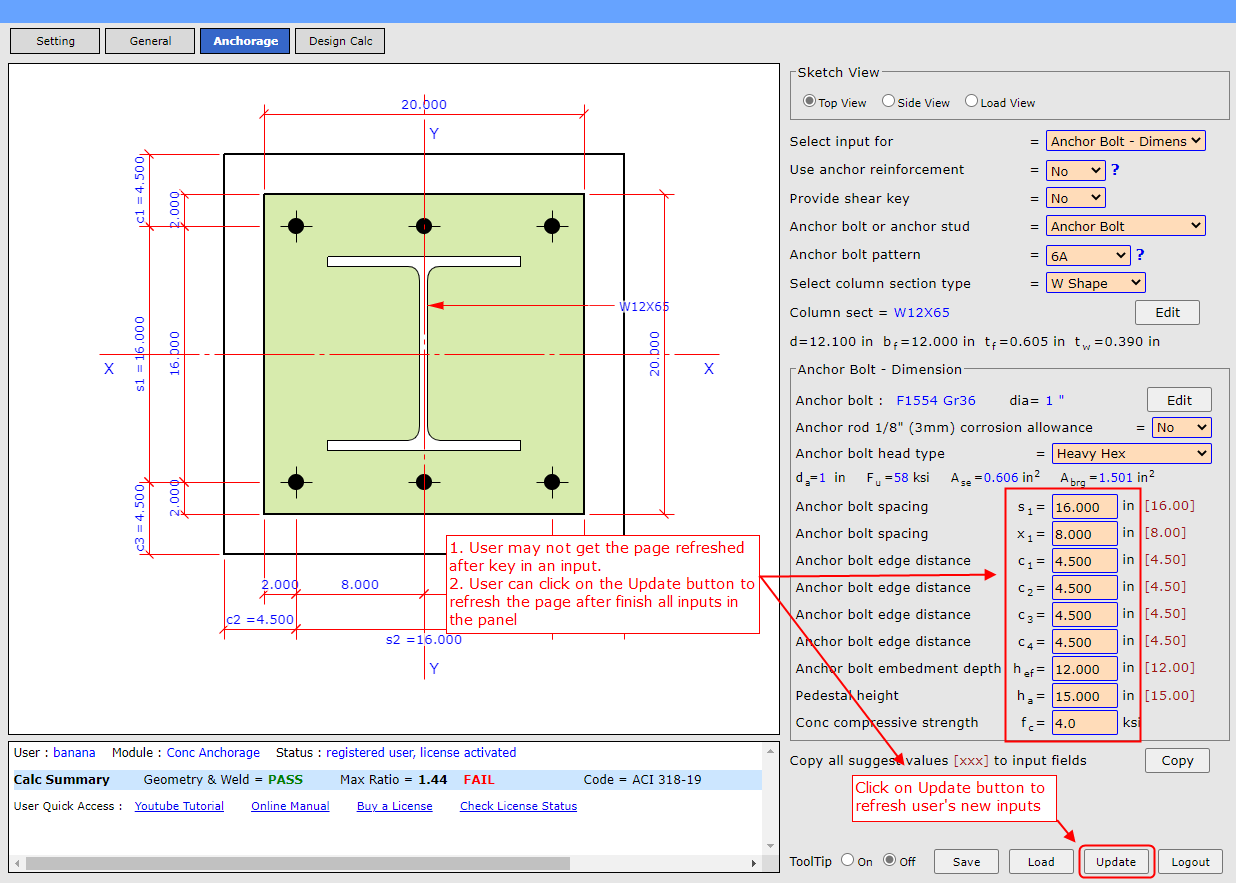
To save time and avoid page refreshing after user keys in every input, for many
input fileds the page remains not updated after user keys in a new value.
User can click on the
Update button to refresh
the page after finish all inputs in the panel.
13. User input and highlighted text in sketch
|
Back to Top
|
User can view
Youtube video on this Tutorial
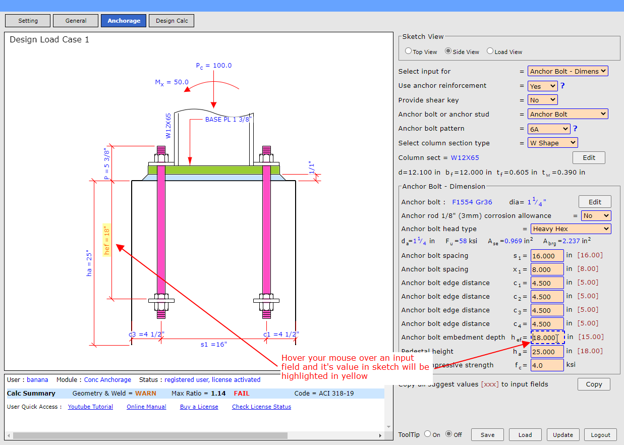
See screenshot below, hover your mouse over an input field and it's value in sketch
will be highlighted in yellow
14. How to use tooltip and turn tooltip On/Off ?
|
Back to Top
|
User can view
Youtube video on this Tutorial
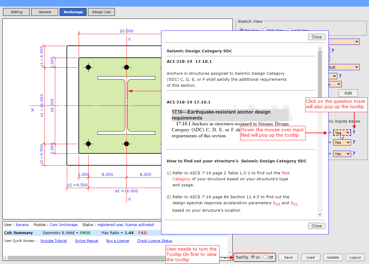
The program provides Tooltip for almost every input fields. It is an online user
manual for user's convenience.
User needs to turn the Tooltip On first before viewing the
tooltip and user can turn it Off after user is familiar with the program.
User can hover the mouse over input filed and it will pop up the tooltip
User can also click on the question mark and it will also pop up the tooltip
15. What is suggest values and how to use them ?
|
Back to Top
|
User can view
Youtube video on this Tutorial
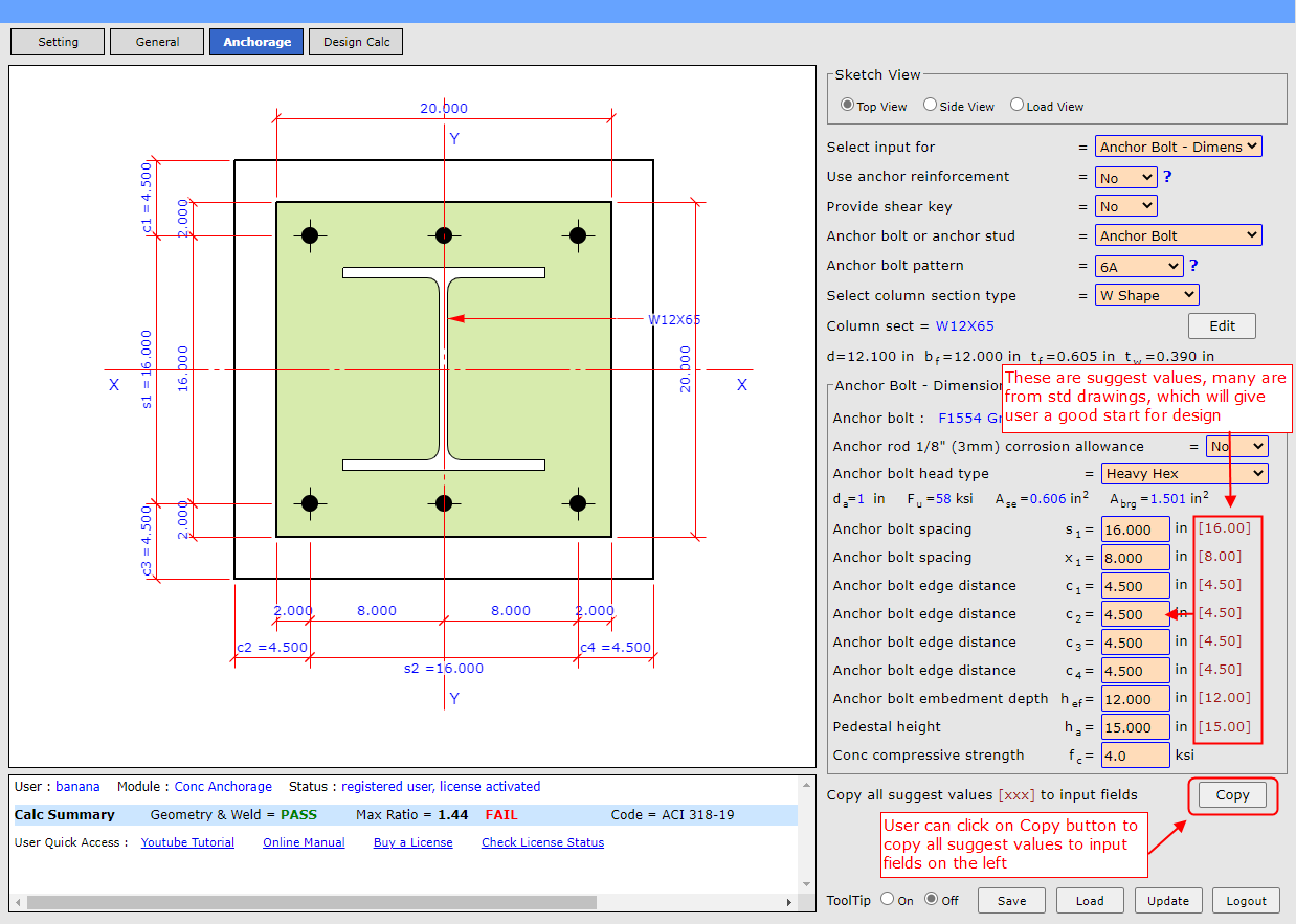
See screenshot below, there are suggest values, many are from standard drawings,
which will give user a good start for design
User can click on
Copy button to copy all suggest
values to input fields on the left
16. How to view and get calculation report
|
Back to Top
|
User can view
Youtube video on this Tutorial
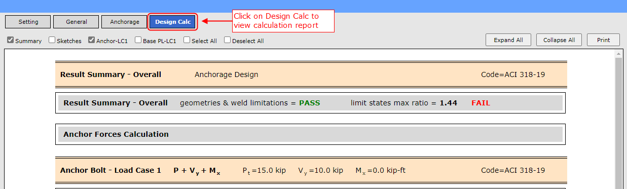
User can click on
Design Calc to view calculation
report as shown on screenshot below.
Refer to next FAQ for details on how to navigate/organize calculation report for
printout.
17. How to arrange calculation report in Summary / Condensed
/ Detailed / Sketch format ?
|
Back to Top
|
User can view
Youtube video on this Tutorial
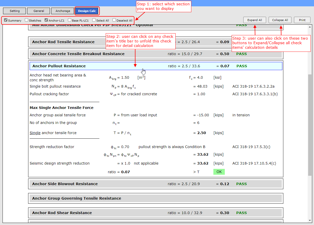
See screenshot below. User can review/organize which section of calculation to be
displayed and click on any check item's title bar to
expand/collapse that item to review detail calculation.
Step 1: User can select which section of calculation to be displayed by checking
items in this checkbox. If only
Summary is checked
then it will
only display result summary, or
Sketches is checked,
it will display sketches.
Step 2: User can click on any check item's title bar to unfold this check item to
show detail calculation
Step 3: User can also click on the
Expand All /
Collapse All to expand/collapse all check items'
calculation details in one single shot
18. How to add company name and project name in calc report
title ?
|
Back to Top
|
User can view
Youtube video on this Tutorial
See Step 3 and Step 4 in next
FAQ-19
on how to add company name and project name in the calculation report
19. How to print calculation report ?
|
Back to Top
|
User can view
Youtube video on this Tutorial
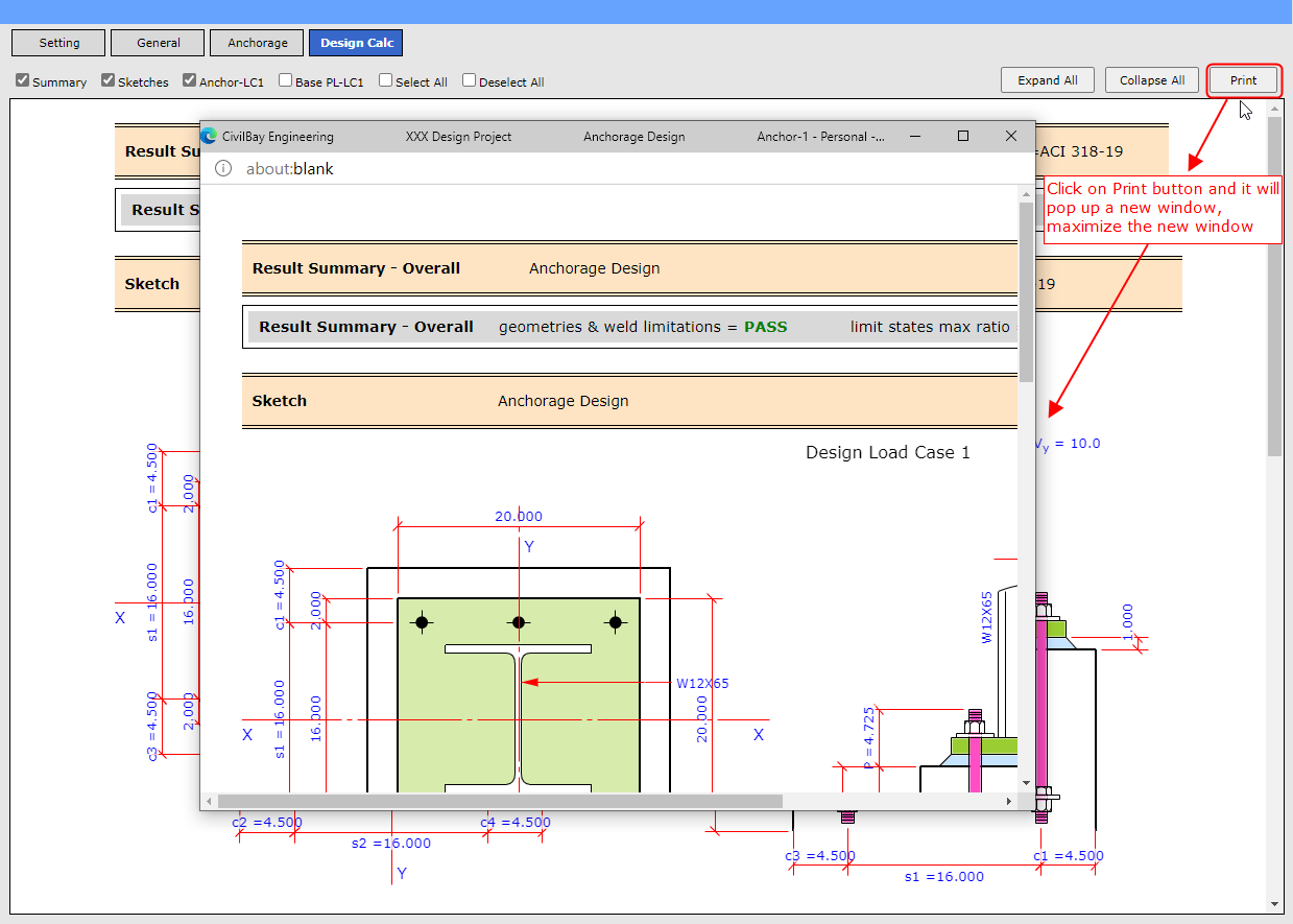
Before printing a calculation report , user may follow
FAQ-16
above to arrange the report in user expected format by checking the
checkboxes and expand/collapse required sections.
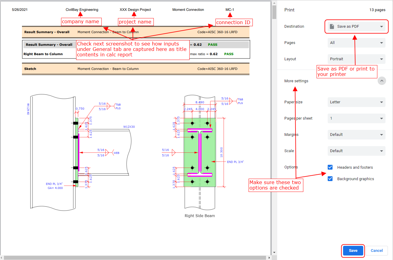
Step 1: In
Design Calc tab, click
on
Print button and it will pop up a new window
as shown in screenshot below, maximize the new window
Step
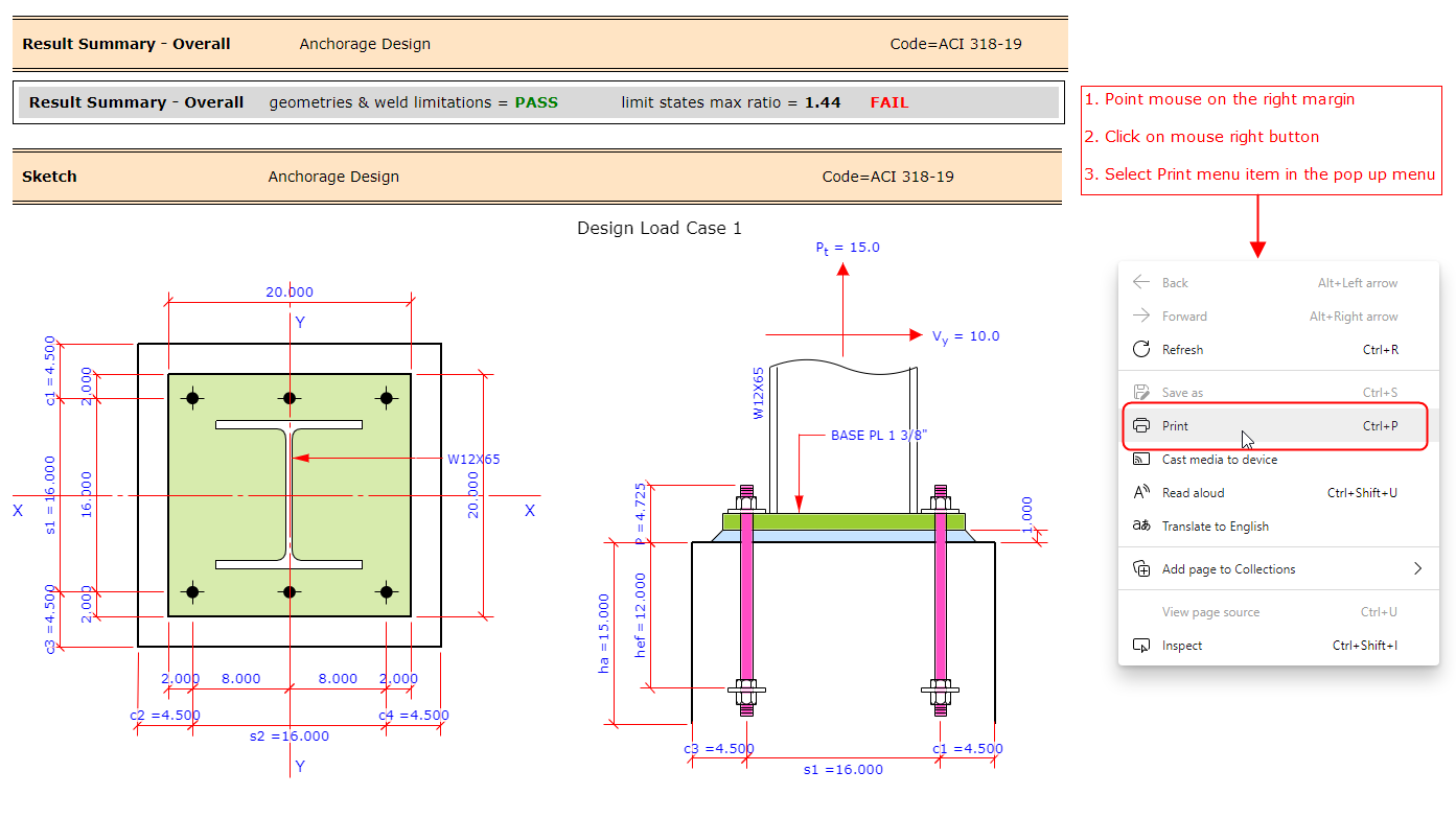
Step 2: Maximize the new window
a) Point mouse on the right
margin b) Click on mouse right button
c) Select Print menu item in the pop up menu
 Step 3:
In the new print window, the two checkbox under bottom-left Options area are checked
by default, if not please check these two options
See next screenshot in Step 4 to understand how the inputs of Company Name, Project
Name and Connection ID under
General tab are captured
here as calculation report title
 Step 4:
Compare to screenshot above to understand how the inputs of Company Name, Project
Name and Connection ID under
General tab are captured
as calculation report title
20. How to save and load input file ?
|
Back to Top
|
User can view
Youtube video on this Tutorial
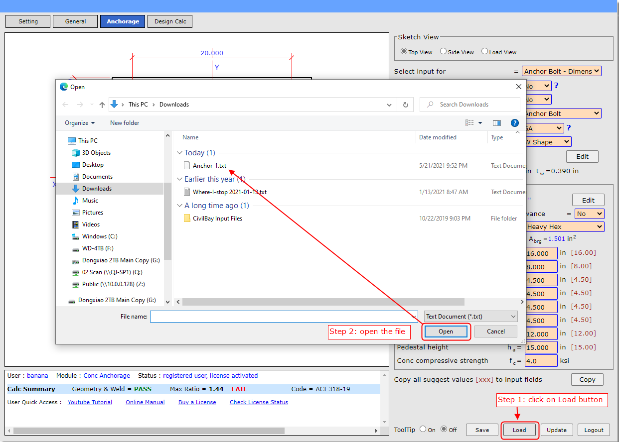
Follow instructions below to open/save an input file.
It's
exactly the same as how you save a download file in the web browser.
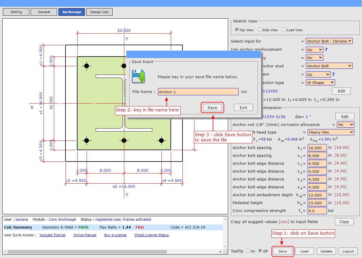
How to save an input file
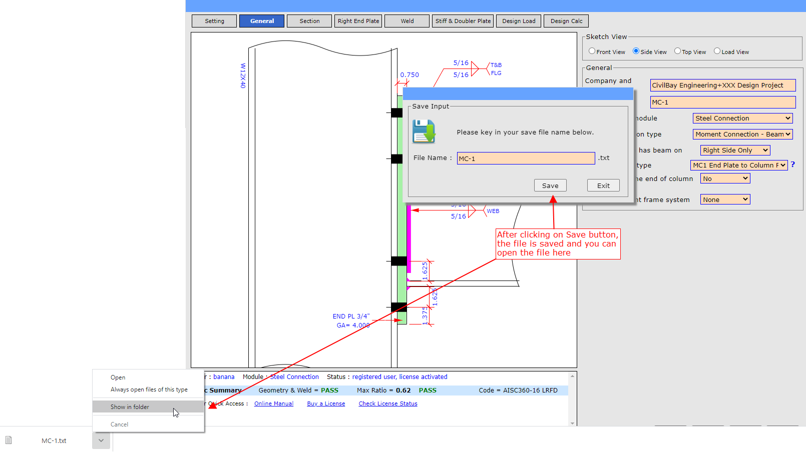
How to open an input file
21. How to select the steel connection type ?
|
Back to Top
|
22. I got an error message when I run the program
|
Back to Top
|
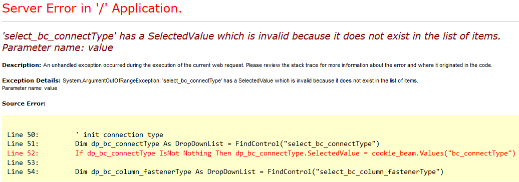
This program may have bugs which will casue error. When you get the error message
similar to the one shown below, don't be panic.
Follow these steps to report the bug to me.
Step 1 : Take a screenshot of the error message similar to the
one below, and email the screenshot to me as attachment of your email
Step 2 : Check this page
How to Reset Program
on how to reset the program. After reset, click on this link
Start Program
to start the program again.
Step 3 : After restart the program, repeat previous steps to reach
the step just before you getting error message, save your input file and email it
to me.
Tell me
for this file on which input you click causes the error. I will fix the bug if I
can repeat your error message here.
Below is a sample error message screenshot. Your error message may not be the same
but shall be similar
25. How to handle transfer force or pass through force
in brace connection
|
Back to Top
|
User can refer to this
tutorial video
and
tutorial page
for detail explanation on how to handle brace transfer/pass through force
input in this program.
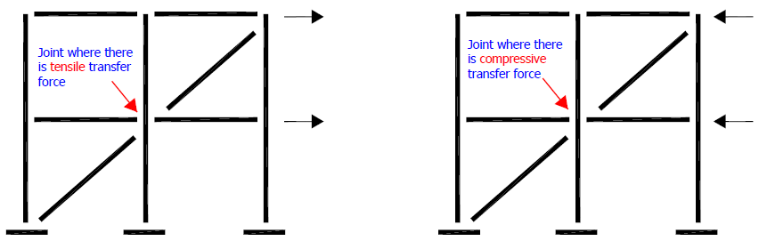
The transfer force or pass through force in brace connection is handled as per schematic
chart shown below.
User can split the brace connection into two sides of brace connection and design
them separately. The relationship between the two sides is the transfer force TF.
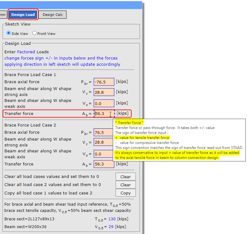
Transfer Force or Pass-through Force Load Input
Transfer force or pass-through force input field takes both +/- value.
Positive value denotes
tensile transfer
force ,
negative value denotes
compressive transfer force.
The author suggests to input
positive transfer
force
all the time for both load input cases .
Positive transfer force will add axial
tensile
force to beam-column interface
axial force so that it will produce conservative result for the brace connection
design.
Beam End Beam Axial Load Input
In one sentence, beam end beam axial load
Pbm , which is taken from structural analysis
member force output, is
NOT required for brace
connection beam-column design.
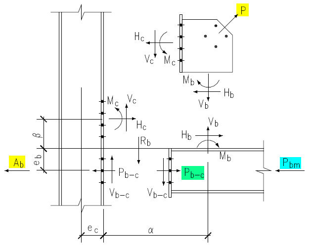
Refer to Gusset Plate Interface Forces Calculation - Uniform Force Method chart
below.
Pbm - beam member axial force, which
is taken from structural analysis member force output, is
NOT needed for brace connection beam-column design
Pb-c - beam to column interface axial
force, which is calculated from user's input of brace axial force
P and trasnfer force
Ab
using uniform force method.
It is
Pb-c
, not
Pbm , that is used in the
brace connection beam-column design
For brace connection load inputs, we expect brace axial force
P , beam end shear load
Vb-c
and trasnfer force
Ab for
load input, but beam end axial load
Pbm
is
not required.
Q1. Steel frame engineer gives out beam axial load
Pbm
and asks connection enginner to use it for brace connection design
Connection enginner shall request trasnfer force
Ab instead of beam end axial load
Pbm . When there is no choice,
connection enginner can take beam axial load
Pbm
and input it as
positive
value of transfer force
Ab
Q2. Steel frame engineer gives out both beam end axial load
Pbm and transfer force
Ab
and asks connection enginner to use them for brace connection design
Brace axial force
P
, trasnfer force
Ab , and beam
axial load
Pbm can
NOT be all from input values at the same time as one of the three can
be derived from the other two.
The author suggests to input
positive transfer
force
all the time for both load input cases .
Positive transfer force will add axial
tensile
force to beam-column interface
axial force so that it will produce conservative result for the brace connection
design.
Below is the load input panel for brace connection
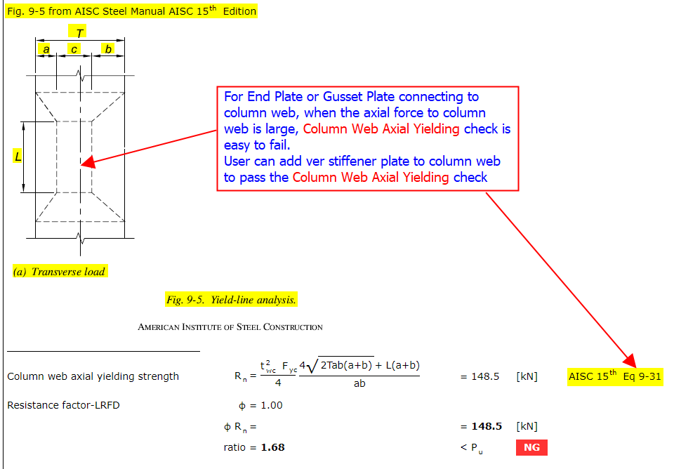
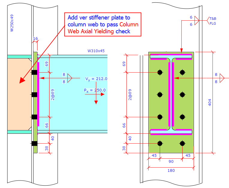
26. Adding column web stiffener to bypass Column Web Axial
Yielding check
|
Back to Top
|
In brace or shear connection where beam connects to
column
web using End Plate, Shear Tab or Gusset Plate as connector, when beam's
axial force imposed on column web is large,
Column Web Axial
Yielding check is very easy to fail.
User can add vertical stiffener plate to column web to waive the
Column Web Axial Yielding check