|
|
|
|
|
|
|
|
|
|
|
|
ANCHOR BOLT DESIGN
|
Combined Tension, Shear and Moment |
|
|
|
Result Summary
|
|
|
|
|
|
|
|
|
|
| Anchor Rod Embedment, Spacing and Edge Distance
|
|
|
|
OK
|
|
| Min Rquired Anchor Reinft. Development Length
|
ratio
|
=
|
0.87
|
OK
|
|
| Overall
|
|
|
|
|
ratio
|
=
|
0.84
|
OK
|
|
| Seismic Design
|
|
|
|
|
Tension
|
=
|
|
OK
|
|
|
|
|
|
|
|
Shear
|
=
|
|
OK
|
|
|
|
Design Code Reference
|
|
|
|
|
|
|
|
|
|
| Anchor bolt design based on
|
|
|
|
|
|
|
|
|
Code Abbreviation
|
| ACI 318-11 Building Code Requirements for Structural Concrete and Commentary Appendix
D
|
ACI 318-11
|
| PIP STE05121 Anchor Bolt Design Guide-2006
|
PIP STE05121
|
| AISC Design Guide 1: Base Plate and Anchor Rod Design 2nd Ed
|
AISC Design Guide 1
|
|
|
|
|
|
|
|
|
|
Code Reference
|
|
Anchor Bolt Data
|
|
|
|
|
|
|
|
|
|
|
| Factored moment |
Mu |
= |
|
[kip-ft] |
|
|
|
|
|
|
| Factored tension or compression
|
Nu
|
=
|
|
[kips]
|
in compression
|
|
|
| Factored shear force
|
Vu
|
=
|
|
[kips]
|
|
|
|
|
|
|
|
|
|
|
|
|
|
|
|
|
| |
|
|
|
|
|
|
|
|
|
|
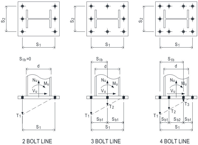
| No of bolt line for resisting moment |
= |
|
|
|
|
|
|
|
| No of bolt along outermost bolt line |
= |
|
|
|
|
|
|
|
| |
|
|
|
|
|
|
|
|
|
|
| Outermost bolt line spacing s1
|
s1
|
=
|
|
[in]
|
4.00
|
|
OK
|
|
Page A -1 Table 1
|
| Outermost bolt line spacing s2
|
s2
|
=
|
|
[in]
|
4.00
|
|
OK
|
|
|
| |
|
|
|
|
|
|
|
|
|
|
| Column depth |
d |
= |
|
[in] |
|
|
|
|
|
|
| |
|
|
|
|
|
|
|
|
|
|
| Concrete strength
|
f'c
|
=
|
|
[ksi]
|
Error: the conc strength shall be 2~10 ksi
|
|
|
| Anchor bolt material
|
|
=
|
|
|
|
|
|
|
| Anchor tensile strength
|
futa
|
=
|
58.0
|
[ksi]
|
|
|
|
|
ACI 318-11
|
|
|
|
|
Anchor is ductile steel element
|
|
|
|
D.1
|
| Anchor bolt diameter
|
da
|
=
|
|
[in]
|
|
|
|
|
|
| Anchor bolt has sleeve
|
|
=
|
|
|
|
|
|
|
PIP STE05121
|
|
|
|
|
|
|
|
|
|
|
|
| Anchor bolt embedment depth
|
hef
|
=
|
|
[in]
|
12.00
|
|
OK
|
|
Page A -1 Table 1
|
| Pedestal height
|
ha
|
=
|
|
[in]
|
17.00
|
|
OK
|
|
|
| Pedestal width
|
bc
|
=
|
|
[in]
|
|
|
|
|
|
| Pedestal depth
|
dc
|
=
|
|
[in]
|
|
|
|
|
|
|
|
|
|
|
|
|
|
|
|
|
|
|
|
|
|
|
|
|
|
|
|
PIP STE05121
|
| Anchor bolt edge distance c1
|
c1
|
=
|
|
[in]
|
4.50
|
|
OK
|
|
Page A -1 Table 1
|
| Anchor bolt edge distance c2
|
c2
|
=
|
|
[in]
|
4.50
|
|
OK
|
|
|
| Anchor bolt edge distance c3
|
c3
|
=
|
|
[in]
|
4.50
|
|
OK
|
|
|
| Anchor bolt edge distance c4
|
c4
|
=
|
|
[in]
|
4.50
|
|
OK
|
|
|
|
|
|
|
|
|
|
|
|
|
|
|
|
|
|
|
|
|
|
|
|
ACI 318-11
|
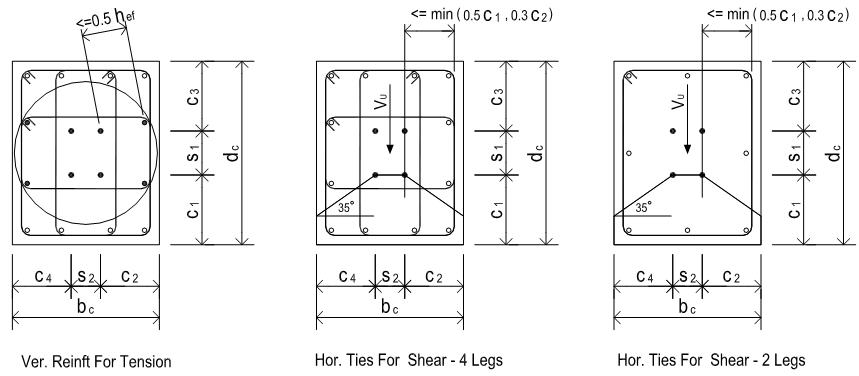
| To be considered effective for resisting anchor tension, vertical reinforcing bars
shall be located
|
RD.5.2.9
|
| within 0.5hef from the outmost anchor's centerline
|
|
| Avg ver. bar center to anchor rod center distance
|
dar
|
=
|
|
[in]
|
|
| No of ver. rebar that are effective for resisting anchor tension
|
nv
|
=
|
|
|
|
| Ver. rebar size No.
|
|
=
|
1.000
|
[in] dia
|
single rebar area As
|
=
|
0.790
|
[in2]
|
|
| Ver. rebar top anchorage option
|
|
|
|
|
|
|
|
|
|
|
|
|
|
|
|
ACI 318-11
|
| To be considered effective for resisting anchor shear, hor. reinft shall be located
|
RD.6.2.9
|
| within min( 0.5c1, 0.3c2 ) from the outmost anchor's centerline
|
min (0.5c1, 0.3c2)
|
=
|
1.50
|
[in]
|
|
|
|
|
|
|
|
|
| No of tie leg that are effective to resist anchor shear
|
nleg
|
=
|
|
|
|
| No of tie layer that are effective to resist anchor shear
|
nlay
|
=
|
|
|
|
| Hor. tie rebar size No.
|
|
=
|
0.500
|
[in] dia
|
single rebar area As
|
=
|
0.200
|
[in2]
|
|
| For anchor reinft shear breakout strength calc
|
|
|
|
|
|
|
|
|
|
|
|
|
|
| Rebar yield strength - ver. rebar
|
fy-v
|
=
|
|
[ksi]
|
|
|
|
|
| Rebar yield strength - hor. rebar
|
fy-h
|
=
|
|
[ksi]
|
|
|
|
|
| Total no of anchor bolt |
n |
= |
|
|
|
|
|
|
| No of anchor bolt carrying tension
|
nt
|
=
|
|
|
|
|
|
|
| No of anchor bolt carrying shear
|
ns
|
=
|
|
|
|
|
|
|
|
|
|
|
|
|
|
|
|
|
|
|
|
|
|
|
|
|
|
|
|
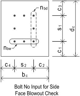
| For side-face blowout check use
|
|
|
|
|
|
|
|
|
| No of anchor bolt along width edge
|
nbw
|
=
|
|
|
|
|
|
|
|
|
|
|
|
|
|
|
|
|
| Anchor bolt head type
|
|
|
|
|
|
| Anchor effective cross section area
|
Ase
|
=
|
0.606
|
[in2]
|
|
|
|
|
| Anchor bolt head bearing area
|
Abrg
|
=
|
|
[in2]
|
|
|
|
|
|
|
|
| Anchor bolt 1/8" (3mm) corrosion allowance
|
=
|
|
|
|
|
|
|
ACI 318-11
|
| Provide built-up grout pad ?
|
|
=
|
|
|
|
|
|
|
D.6.1.3
|
|
|
|
|
|
|
|
|
|
|
|
| Seismic design category SDC >= C
|
|
=
|
|
|
|
|
|
|
D.3.3.1
|
| Anchor bolt load E <= 0.2U
|
Tensile
|
=
|
|
|
Shear
|
=
|
|
|
D.3.3.4.1 & D.3.3.5.1
|
| Anchor bolt satisfies opion
|
Tensile
|
=
|
|
Shear
|
=
|
|
D.3.3.4.3 & D.3.3.5.3
|
|
|
|
|
|
|
|
|
|
|
|
| Strength reduction factors
|
|
|
|
|
|
|
|
|
ACI 318-11
|
| Anchor reinforcement
|
fs
|
=
|
0.75
|
|
|
|
|
|
D.5.2.9 & D.6.2.9
|
| Anchor rod - ductile steel
|
ft,s
|
=
|
0.75
|
|
fv,s
|
=
|
0.65
|
|
D.4.3 (a)
|
| Concrete - condition A
|
ft,c
|
=
|
0.75
|
|
fv,c
|
=
|
0.75
|
|
D.4.3 (c)
|
|
|
CONCLUSION
|
|
|
|
|
|
|
|
|
|
| Anchor Rod Embedment, Spacing and Edge Distance
|
|
|
|
OK
|
ACI 318-11
|
| Min Rquired Anchor Reinft. Development Length
|
ratio
|
=
|
0.87
|
OK
|
12.5.1
|
|
Overall
|
ratio
|
=
|
0.84
|
OK
|
|
|
Tension
|
|
|
|
|
|
| Anchor Rod Tensile Resistance
|
ratio
|
=
|
0.31
|
OK
|
|
| Anchor Reinft Tensile Breakout Resistance
|
ratio
|
=
|
0.15
|
OK
|
|
| Anchor Pullout Resistance
|
ratio
|
=
|
0.25
|
OK
|
|
| Side Blowout Resistance
|
ratio
|
=
|
0.27
|
OK
|
|
|
Shear
|
|
|
|
|
|
| Anchor Rod Shear Resistance
|
ratio
|
=
|
0.57
|
OK
|
|
| Anchor Reinft Shear Breakout Resistance
|
|
|
|
|
|
| Strut Bearing Strength
|
ratio
|
=
|
0.45
|
OK
|
|
| Tie Reinforcement
|
ratio
|
=
|
0.69
|
OK
|
|
| Conc. Pryout Not Govern When hef >= 12da
|
|
|
|
OK
|
|
|
Tension Shear Interaction
|
|
|
|
|
|
| Tension Shear Interaction
|
ratio
|
=
|
0.84
|
OK
|
|
|
|
|
|
|
|
|
|
Seismic Design
|
|
|
|
|
ACI 318-11
|
|
Tension
|
Applicable
|
|
|
|
OK
|
D.3.3.4
|
|
Seismic SDC>=C and E>0.2U , Option D is selected to satisfy additional seismic requirements as per D.3.3.4.3
|
|
|
|
|
|
|
|
|
|
|
|
|
|
|
Shear
|
Applicable
|
|
|
|
OK
|
D.3.3.5
|
|
Seismic SDC>=C and E>0.2U , Option C is selected to satisfy additional seismic requirements as per D.3.3.5.3
|
|
|
|
|
Assumptions
|
ACI 318-11
|
| 1. Concrete is cracked
|
D.5.2.6, D5.3.6, D.6.2.7
|
| 2. Condition A - supplementary reinforcement is provided
|
D.4.3 (c)
|
| 3. Load combinations shall be per ACI 318-11 9.2
|
D.4.3
|
| 4. Anchor reinft strength is used to replace concrete tension / shear breakout strength
as per
|
D.5.2.9 & D.6.2.9
|
| ACI 318-11 Appendix D clause D.5.2.9 and D.6.2.9
|
|
| 5. For tie reinft, only the top most 2 or 3 layers of ties (2" from TOC and
2x3" after) are effective
|
|
| 6. Strut-and-Tie model is used to anlyze the shear transfer and to design the required
tie reinft
|
|
| 7. For anchor group subject to moment, the anchor tensile load is designed using elastic analysis |
D.3.1 |
| and there is no redistribution of the forces between highly stressed and less stressed anchors |
|
| 8. For anchor tensile force calc in anchor group subject to moment, assume the compression |
|
| resultant is at the outside edge of the compression flange and base plate exhibits rigid-body
|
|
| rotation. This simplified approach yields conservative output |
|
| 9. Anchor reinft used in structures with SDC>=C shall meet requirements specified
in D.3.3.7
|
D.3.3.7
|
|
10. Anchor bolt washer shall be tack welded to base plate for all anchor bolts to transfer shear
|
AISC Design Guide 1
|
|
|
Section 3.5.3
|
|
|
CACULATION
|
|
|
|
|
|
|
|
|
|
|
Anchor Tensile Force |
|
|
|
|
|
|
|
|
|
| Single bolt tensile force |
T1 |
= |
|
[kips] |
No of bolt for T1 nT1 |
= |
2.0
|
|
|
| Sum of bolt tensile force |
Nu |
= |
S ni Ti |
|
|
= |
16.48
|
[kips] |
|
| |
|
|
|
|
|
|
|
|
|
|
Anchor Rod Tensile Resistance
|
|
|
|
|
|
|
|
|
ACI 318-11
|
|
|
f t,s Nsa
|
=
|
f t,s Ase futa
|
=
|
26.36
|
[kips]
|
D.5.1.2 (D-2)
|
|
|
ratio
|
=
|
0.31
|
>
|
T1 |
OK
|
|
|
|
|
|
|
|
|
|
|
|
Anchor Reinft Tensile Breakout Resistance
|
|
|
|
ACI 318-11
|
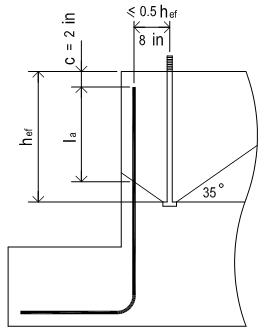
| Min required full yield tension ldh
|
ldh
|
=
|
180 degree hook case
|
=
|
|
[in]
|
12.5.2, 12.5.3(a)
|
| Actual development lenngth
|
la
|
=
|
hef - c (2 in) - dar x tan35
|
=
|
|
[in]
|
|
|
|
|
|
|
>
|
8.00
|
OK
|
12.5.1
|
|
|
|
|
|
|
|
|
|
ACI 318-11
|
| Anchor reinft breakout resistance
|
fs Nn
|
=
|
fs x fy-v x nv x As
x (la / ld , if la < ld)
|
=
|
112.30
|
[kips]
|
D.3.3.4.5, D.5.2.9, 12.2.5
|
|
|
ratio
|
=
|
0.15
|
>
|
Nu
|
OK
|
|
|
|
|
|
|
|
|
|
|
|
Anchor Pullout Resistance
|
|
|
|
|
|
|
ACI 318-11
|
| Single bolt pullout resistance
|
N p
|
=
|
8 Abrg fc'
|
=
|
62.44
|
[kips]
|
D.5.3.4 (D-14)
|
|
|
ft,c Npn
|
=
|
f t,c Ψc,p Np
|
=
|
43.71
|
[kips]
|
D.5.3.1 (D-13)
|
|
|
Ψc,p
|
=
|
1 for cracked conc
|
|
|
|
D.5.3.6
|
|
|
f t,c
|
=
|
0.70
|
pullout strength is always Condition B
|
D.4.3(c)
|
| Seismic design strength reduction
|
|
=
|
x 0.75 applicable
|
=
|
32.78
|
[kips]
|
D.3.3.4.4
|
|
|
ratio
|
=
|
0.25
|
>
|
T1
|
OK
|
|
|
|
|
|
|
|
|
|
|
|
Side Blowout Resistance
|
|
|
|
|
|
|
|
| Failure Along Pedestal Width Edge
|
|
|
|
|
|
|
ACI 318-11
|
| Tensile load carried by anchors close to edge which may cause side-face blowout
|
|
|
|
|
| along pedestal width edge
|
Nbuw
|
=
|
nT1 x T1
|
=
|
16.48
|
[kips]
|
RD.5.4.2
|
|
|
c
|
=
|
min ( c1 , c3 )
|
=
|
5.00
|
[in]
|
|
|
|
s
|
=
|
s2
|
=
|
16.00
|
[in]
|
|
| Check if side blowout applicable
|
hef
|
=
|
14.00
|
[in]
|
|
|
|
|
|
|
|
|
>
|
2.5c
|
side bowout is applicable
| D.5.4.1
|
|
|
|
|
|
|
|
|
|
| Group side blowout resistance
|
ftc Nsbg
|
=
|
|
=
|
60.96
|
[kips]
|
|
|
|
|
|
|
|
|
|
|
|
Govern Tensile Resistance
|
Nr
|
=
|
min ( f nt Nsa, f
Nn, f nt Npn, f
Nsbg )
|
=
|
52.72
|
[kips]
|
|
|
|
|
|
|
|
|
|
|
|
Anchor Rod Shear Resistance
|
|
|
|
|
|
|
ACI 318-11
|
|
|
f v,sVsa
|
=
|
f v,s ns 0.6 Ase futa
|
=
|
54.83
|
[kips]
|
D.6.1.2 (b) (D-29)
|
| Reduction due to built-up grout pad
|
|
=
|
x 0.8 , applicable
|
=
|
43.86
|
[kips]
|
D.6.1.3
|
|
|
ratio
|
=
|
0.57
|
>
|
Vu
|
OK
|
|
|
|
|
|
|
|
|
|
|
|
Anchor Reinft Shear Breakout Resistance
|
|
|
|
ACI 318-11
|
| Strut-and-Tie model is used to anlyze the shear transfer and to design the required
tie reinft
|
|
| STM strength reduction factor
|
fst
|
=
|
0.75
|
|
|
|
9.3.2.6
|
|
|
|
|
|
|
|
|
|
|
|
|
|
|
|
|
|
|
|
| Strut-and-Tie model geometry
|
dv
|
=
|
2.250
|
[in]
|
dh
|
=
|
2.250
|
[in]
|
|
|
|
θ
|
=
|
45
|
|
dt
|
=
|
3.182
|
[in]
|
|
| Strut compression force
|
Cs
|
=
|
0.5 Vu / sinθ
|
=
|
17.68
|
[kips]
|
|
|
|
|
|
|
|
|
|
|
|
Strut Bearing Strength
|
|
|
|
|
|
|
ACI 318-11
|
| Strut compressive strength
|
fce
|
=
|
0.85 f'c
|
=
|
4.4
|
[ksi]
|
A.3.2 (A-3)
|
|
|
|
|
|
|
|
|
|
| * Bearing of anchor bolt
|
|
|
|
|
|
|
|
| Anchor bearing length
|
le
|
=
|
min( 8da , hef )
|
=
|
8.00
|
[in]
|
D.6.2.2
|
| Anchor bearing area
|
Abrg
|
=
|
le x da
|
=
|
8.00
|
[in2]
|
|
| Anchor bearing resistance
|
Cr
|
=
|
ns x fst x fce x Abrg
|
=
|
106.08
|
[kips]
|
|
|
|
|
|
|
>
|
Vu
|
OK
|
|
| * Bearing of ver reinft bar
|
|
|
|
|
|
|
|
| Ver bar bearing area
|
Abrg
|
=
|
(le +1.5 x dt - da/2 -db/2) x db
|
=
|
11.77
|
[in2]
|
|
| Ver bar bearing resistance
|
Cr
|
=
|
fst x fce x Abrg
|
=
|
39.03
|
[kips]
|
|
|
|
ratio
|
=
|
0.45
|
>
|
Cs
|
OK
|
|
|
|
|
|
|
|
|
|
|
|
Tie Reinforcement
|
|
|
|
|
|
|
|
| * For tie reinft, only the top most 2 or 3 layers of ties (2" from TOC and
2x3" after) are effective
|
| * For enclosed tie, at hook location the tie cannot develop full yield strength
fy . Use the pullout resistance in
|
| tension of a single hooked bolt as per ACI 318-11 Eq. (D-15)
as the max force can be developed at hook Th
|
|
* Assume 100% of hor. tie bars can develop full yield strength
|
|
|
| Total number of hor tie bar
|
n
|
=
|
nleg (leg) x nlay (layer)
|
=
|
4
|
|
|
|
|
|
|
|
|
|
|
ACI 318-11
|
| Pull out resistance at hook
|
Th
|
=
|
ft,c 0.9 fc' eh
da
|
=
|
3.95
|
[kips]
|
D.5.3.5 (D-15)
|
|
|
eh
|
=
|
4.5 db
|
=
|
2.250
|
[in]
|
|
|
|
|
|
|
|
|
|
|
| Single tie bar tension resistance
|
Tr
|
=
|
fs x fy-h x As
|
=
|
9.00
|
[kips]
|
|
|
|
|
|
|
|
|
|
|
| Total tie bar tension resistance
|
fsVn
|
=
|
1.0 x n x Tr
|
=
|
36.00
|
[kips]
|
D.3.3.5.4 & D.6.2.9
|
|
|
ratio
|
=
|
0.69
|
>
|
Vu
|
OK
|
|
|
|
|
|
|
|
|
|
|
|
Conc. Pryout Shear Resistance
|
|
|
|
|
|
|
|
| The pryout failure is only critical for short and stiff anchors. It is reasonable
to assume that for general
|
| cast-in place headed anchors with hef > = 12da , the pryout
failure will not govern
|
|
|
|
|
|
|
|
|
|
|
|
12da
|
=
|
12.00
|
[in]
|
hef
|
=
|
14.00
|
[in]
|
|
|
|
|
|
|
>
|
12da
|
OK
|
|
|
|
|
|
|
|
|
|
|
|
Govern Shear Resistance
|
Vr
|
=
|
min ( fv,sVsa , fsVn )
|
=
|
36.00
|
[kips]
|
|
|
|
|
|
|
|
|
|
|
|
Tension Shear Interaction
|
|
|
|
|
|
|
ACI 318-11
|
| Check if Nu >0.2f Nn and Vu
>0.2f Vn
|
=
|
Yes
|
|
|
|
D.7.1 & D.7.2
|
|
|
|
|
Nu / f Nn + Vu / f Vn
|
=
|
1.01
|
|
D.7.3 (D-42)
|
|
|
ratio
|
=
|
0.84
|
<
|
1.2
|
OK
|
|
|
|
|
|
|
|
|
|
|
|
Seismic Design
|
|
|
|
|
|
|
|
|
Tension
|
|
|
Applicable
|
|
|
OK
|
|
| Option D is selected.
|
ACI 318-11
|
User has to ensure that the tensile load Nu user input above includes
the seismic load E, with E increased
by multiplying overstrength factor Ωo
|
D.3.3.4.3(d)
|
|
|
|
|
|
|
|
|
|
|
|
|
Seismic SDC>=C and E>0.2U , Option D is selected to satisfy additional seismic requirements as per D.3.3.4.3
|
|
|
|
|
|
|
|
|
|
|
|
|
Shear
|
|
|
Applicable
|
|
|
OK
|
|
| Option C is selected.
|
|
|
|
|
|
|
ACI 318-11
|
User has to ensure that the shear load Vu user input above includes the
seismic load E, with E increased
by multiplying overstrength factor Ωo
|
D.3.3.5.3(c)
|
|
|
|
|
|
|
|
|
|
|
Seismic SDC>=C and E>0.2U , Option C is selected to satisfy additional seismic requirements as per D.3.3.5.3
|
|
|
|
|
|
|
|
|
|
|
|
|
|
|