|
|
|
|
|
|
|
|
|
|
|
|
ANCHOR BOLT DESIGN
|
Combined Tension, Shear and Moment |
|
|
|
Result Summary
|
|
|
|
|
|
|
|
|
|
| Anchor Rod Embedment, Spacing and Edge Distance
|
|
|
|
Warn
|
|
| Overall
|
|
|
|
|
ratio
|
=
|
0.76
|
OK
|
|
| Seismic Design
|
|
|
|
|
Tension
|
=
|
|
OK
|
|
|
|
|
|
|
|
Shear
|
=
|
|
OK
|
|
|
|
Design Code Reference
|
|
|
|
|
|
|
|
|
|
| Anchor bolt design based on
|
|
|
|
|
|
|
|
|
Code Abbreviation
|
| ACI 318M-11 Building Code Requirements for Structural Concrete and Commentary Appendix
D
|
ACI 318M-11
|
| PIP STE05121 Anchor Bolt Design Guide-2006
|
PIP STE05121
|
| AISC Design Guide 1: Base Plate and Anchor Rod Design 2nd Ed
|
AISC Design Guide 1
|
|
Anchor Bolt Data
|
|
|
|
|
|
|
|
|
Code Reference
|
| Factored moment |
Mu |
= |
|
[kNm] |
|
|
|
|
|
|
| Factored tension or compression
|
Nu
|
=
|
|
[kN]
|
in compression
|
|
|
| Factored shear force
|
Vu
|
=
|
|
[kN]
|
|
|
|
|
|
|
|
|
|
|
|
|
|
|
|
|
| |
|
|
|
|
|
|
|
|
|
|
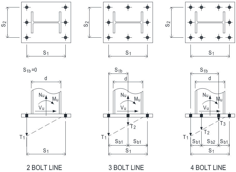
| No of bolt line for resisting moment |
= |
|
|
|
|
|
|
|
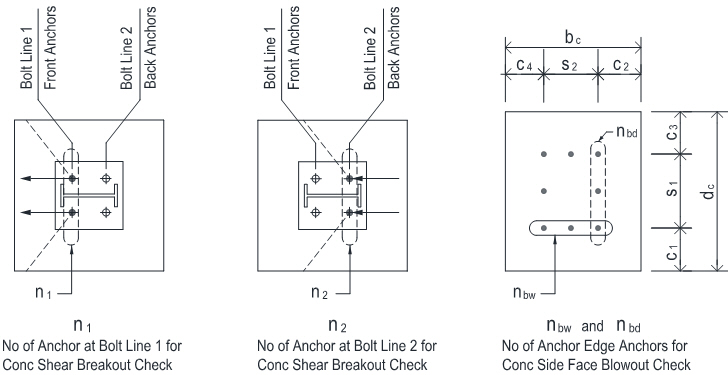
| No of bolt along outermost bolt line |
= |
|
|
|
|
|
|
|
| No of bolt along side edge |
nbd |
= |
|
|
|
|
|
|
|
|
| |
|
|
|
|
|
|
|
|
PIP STE05121
|
| Outermost bolt line spacing s1
|
s1
|
=
|
|
[mm]
|
102
|
|
OK
|
|
Page A -1 Table 1
|
| Outermost bolt line spacing s2
|
s2
|
=
|
|
[mm]
|
102
|
|
OK
|
|
|
| Max spacing between anchors in tension |
= |
|
[mm] |
|
|
|
|
|
|
| |
|
|
|
|
|
|
|
|
|
|
| Column depth |
d |
= |
|
[mm] |
|
|
|
|
|
|
| Concrete strength
|
f'c
|
=
|
|
[MPa]
|
Error: the conc strength shall be 10~70 MPa
|
|
|
| Anchor bolt material
|
|
=
|
|
|
|
|
|
|
| Anchor tensile strength
|
futa
|
=
|
400
|
[MPa]
|
|
|
|
|
ACI 318M-11
|
|
|
|
|
Anchor is ductile steel element
|
|
|
|
D.1
|
| Anchor bolt diameter
|
da
|
=
|
|
[in]
|
|
=
|
25.4
|
[mm] |
|
| Anchor bolt has sleeve
|
|
=
|
|
|
|
|
|
|
PIP STE05121
|
|
|
|
|
|
|
|
|
|
|
PIP STE05121
|
| Anchor bolt edge distance c1
|
c1
|
=
|
|
[mm]
|
114
|
|
OK
|
|
Page A -1 Table 1
|
| Anchor bolt edge distance c2
|
c2
|
=
|
|
[mm]
|
114
|
|
OK
|
|
|
| Anchor bolt edge distance c3
|
c3
|
=
|
|
[mm]
|
114
|
|
OK
|
|
|
| Anchor bolt edge distance c4
|
c4
|
=
|
|
[mm]
|
114
|
|
OK
|
|
|
| |
|
|
|
|
|
|
|
|
|
| Anchor bolt embedment depth
|
hef
|
=
|
|
[mm]
|
|
|
|
|
ACI 318M-11
|
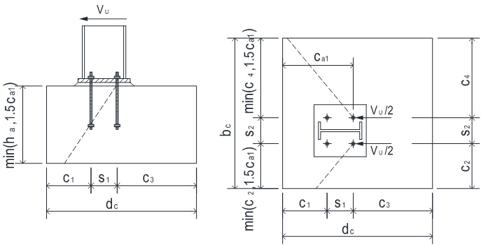
| ci ≥ 1.5hef for at least two edges to avoid reducing of hef when Nu > 0 |
|
Warn
|
|
D.5.2.3 |
| Anchor bolt adjusted hef for design |
hef |
= |
|
[mm]
|
305
|
|
Warn
|
|
D.5.2.3 |
| Concrete thickness |
ha
|
=
|
|
[mm]
|
381
|
|
Warn
|
|
|
| |
|
|
|
|
|
|
|
|
|
| |
|
|
|
|
|
|
|
|
|
|
|
| |
|
|
|
|
|
|
|
|
|
| For conc shear breakout check use
|
|
|
|
|
|
|
|
|
|
| Number of anchor at bolt line 1 |
n1 |
=
|
|
|
|
|
|
|
|
| Number of anchor at bolt line 2 |
n2 |
= |
|
|
|
|
|
|
|
| |
|
|
|
|
|
|
|
|
| Total no of anchor bolt |
n |
= |
|
|
|
|
|
|
| No of anchor bolt carrying tension
|
nt
|
=
|
|
|
|
|
|
|
|
| No of anchor bolt carrying shear
|
ns
|
=
|
|
|
|
|
|
|
|
| Oversized holes in base plate ? |
|
= |
|
|
|
|
|
|
|
|
|
|
|
|
|
|
|
|
|
|
| Anchor bolt head type
|
|
|
|
|
|
| Anchor effective cross section area
|
Ase
|
=
|
391
|
[mm2]
|
|
|
|
|
| Anchor bolt head bearing area
|
Abrg
|
=
|
|
[mm2]
|
|
|
|
|
|
|
|
| Anchor bolt 1/8" (3mm) corrosion allowance
|
=
|
|
|
|
|
|
|
|
| Supplementary reinforcement |
|
|
|
|
|
|
|
|
ACI 318M-11
|
| For tension |
|
= |
|
Condition A
|
|
|
|
D.4.3 (c) |
| For shear |
Yc,v |
= |
|
Condition A
|
|
|
|
D.6.2.7 |
| |
|
|
|
|
|
|
|
|
ACI 318M-11
|
| Provide built-up grout pad ?
|
|
=
|
|
|
|
|
|
|
D.6.1.3
|
| Concrete cracking |
|
= |
|
|
|
|
|
D.5.2.6, D5.3.6, D.6.2.7 |
| |
|
|
|
|
|
|
|
|
ACI 318M-11
|
| Seismic design category SDC >= C
|
|
=
|
|
|
|
|
|
|
D.3.3.1
|
| Anchor bolt load E <= 0.2U
|
Tensile
|
=
|
|
|
Shear
|
=
|
|
|
D.3.3.4.1 & D.3.3.5.1
|
| Anchor bolt satisfies opion
|
Tensile
|
=
|
|
Shear
|
=
|
|
D.3.3.4.3 & D.3.3.5.3
|
|
|
|
|
|
|
|
|
|
|
|
| Strength reduction factors
|
|
|
|
|
|
|
|
|
ACI 318M-11
|
| Anchor reinforcement
|
fs
|
=
|
0.75
|
|
|
|
|
|
D.5.2.9 & D.6.2.9
|
| Anchor rod - ductile steel
|
ft,s
|
=
|
0.75
|
|
fv,s
|
=
|
0.65
|
|
D.4.3 (a)
|
| Concrete |
ft,c
|
=
|
0.75 Cdn-A
|
fv,c
|
=
|
0.75 Cdn-A
|
D.4.3 (c)
|
|
|
CONCLUSION
|
|
|
|
|
|
|
|
|
|
| Anchor Rod Embedment, Spacing and Edge Distance
|
|
|
|
Warn
|
|
|
Overall
|
ratio
|
=
|
0.76
|
OK
|
|
|
Tension
|
|
|
|
|
|
| Anchor Rod Tensile Resistance
|
ratio
|
=
|
0.11
|
OK
|
|
| Concrete Tensile Breakout Resistance |
ratio
|
=
|
0.41
|
OK
|
|
| Anchor Pullout Resistance
|
ratio
|
=
|
0.09
|
OK
|
|
| Side Blowout Resistance
|
ratio
|
=
|
0.00
|
NA
|
|
|
Shear
|
|
|
|
|
|
| Anchor Rod Shear Resistance
|
ratio
|
=
|
0.11
|
OK
|
|
| Concrete Shear Breakout Resistance - Perpendicular To Edge |
ratio
|
=
|
0.51
|
OK
|
|
| Concrete Shear Breakout Resistance - Parallel To Edge |
ratio
|
=
|
0.24
|
OK
|
|
| Concrete Pryout Shear Resistance |
ratio
|
= |
0.19
|
OK
|
|
|
Tension Shear Interaction
|
|
|
|
|
|
| Tension Shear Interaction
|
ratio
|
=
|
0.76
|
OK
|
|
|
|
|
|
|
|
|
|
Seismic Design
|
|
|
|
|
ACI 318M-11
|
|
Tension
|
Applicable
|
|
|
|
OK
|
D.3.3.4
|
|
Seismic SDC>=C and E>0.2U , Option D is selected to satisfy additional seismic requirements as per D.3.3.4.3
|
|
|
|
|
|
|
|
|
|
|
|
|
|
|
Shear
|
Applicable
|
|
|
|
OK
|
D.3.3.5
|
|
Seismic SDC>=C and E>0.2U , Option C is selected to satisfy additional seismic requirements as per D.3.3.5.3
|
|
|
|
|
Assumptions
|
ACI 318M-11
|
|
1. Concrete is cracked
|
D.5.2.6, D5.3.6, D.6.2.7
|
|
2. Condition A - supplementary reinforcement provided
|
D.4.3 (c)
|
| 3. Load combinations shall be per ACI 318M-11 9.2
|
D.4.3
|
| 4. Shear load acts through center of bolt group Yec,V =1.0 |
D.6.2.5 |
| 5. For anchor group subject to moment, the anchor tensile load is designed using elastic analysis |
D.3.1 |
| and there is no redistribution of the forces between highly stressed and less stressed anchors |
|
| 6. For anchor tensile force calc in anchor group subject to moment, assume the compression |
|
| resultant is at the outside edge of the compression flange and base plate exhibits rigid-body
|
|
| rotation. This simplified approach yields conservative output |
|
|
7. Anchor bolt washer shall be tack welded to base plate for all anchor bolts to transfer shear
|
AISC Design Guide 1
|
|
|
Section 3.5.3
|
|
|
CACULATION
|
|
|
|
|
|
|
|
|
|
|
Anchor Tensile Force |
|
|
|
|
|
|
|
|
|
| Single bolt tensile force |
T1 |
= |
|
[kN] |
No of bolt for T1 nT1 |
= |
2.0
|
|
|
| Sum of bolt tensile force |
Nu |
= |
S ni Ti |
|
|
= |
25.0
|
[kN] |
|
| |
|
|
|
|
|
|
|
|
|
| Tensile bolts outer distance stb |
stb |
= |
|
[mm] |
|
|
|
|
|
| Eccentricity e'N -- distance between resultant of tensile load and centroid of anchors |
|
| loaded in tension |
e'N |
= |
|
[mm] |
|
|
|
|
|
| Eccentricity modification factor |
Ψec,N |
= |

|
|
|
= |
1.00
|
|
|
| |
|
|
|
|
|
|
|
|
|
|
Anchor Rod Tensile Resistance
|
|
|
|
|
|
|
|
|
ACI 318M-11
|
|
|
f t,s Nsa
|
=
|
f t,s Ase futa
|
=
|
117.3
|
[kN]
|
D.5.1.2 (D-2)
|
|
|
ratio
|
=
|
0.11
|
>
|
T1
|
OK
|
|
|
|
|
|
|
|
|
|
|
|
Concrete Tensile Breakout Resistance |
|
|
|
ACI 318M-11
|
| |
Nb |
= |
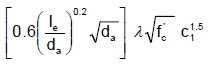
10 l
√fc hef1.5 if hef <280 or hef>635
|
= |
94.2
|
[kN]
|
D.5.2.2 (D-6) |
| |
|
|
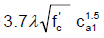
3.9 l √fc hef(5/3) if 280≤ hef ≤635 |
|
|
|
D.5.2.2 (D-7) |
| Projected conc failure area |
1.5 hef |
= |
|
= |
203
|
[mm] |
|
| |
ANC |
= |
[stb+min(c1,1.5hef)+min(c3,1.5hef)]x |
= |
2.2E+05
|
[mm2] |
|
| |
|
|
[s2+min(c2,1.5hef)+min(c4,1.5hef)] |
|
|
|
|
| |
ANCO |
= |
9 hef2 |
= |
1.6E+05
|
[mm2] |
D.5.2.1 (D-5) |
| |
ANC |
= |
min ( ANC, nt ANCO ) |
= |
2.2E+05
|
[mm2] |
D.5.2.1 |
| Min edge distance |
cmin |
= |
min( c1, c2, c3, c4 ) |
= |
125
|
[mm] |
|
| Eccentricity effects |
Ψec,N |
= |
|
= |
1.00
|
|
D.5.2.4 |
| Edge effects |
Ψed,N |
= |
min[ (0.7+0.3cmin/1.5hef), 1.0 ] |
= |
0.88
|
|
D.5.2.5 |
| Concrete cracking |
Ψc,N |
= |
1 for cracked concrete
|
|
|
|
D.5.2.6 |
| Concrete splitting |
Ψcp,N |
= |
1.00 for cast-in anchor |
|
|
|
D.5.2.7 |
| |
|
|
|
|
|
|
|
| Concrete breakout resistance |
ftcNcbg |
= |
|
ftc |
ANC |
Ψec,N Ψed,N Ψc,N Ψcp,N Nb |
| ANCO |
|
= |
81.6
|
[kN]
|
D.5.2.1 (D-4) |
| |
|
|
|
|
|
|
|
| Seismic design strength reduction |
|
= |
x 0.75 applicable
|
= |
61.2
|
[kN]
|
D.3.3.4.4 |
|
|
ratio
|
=
|
0.41
|
>
|
Nu
|
OK
|
|
|
|
|
|
|
|
|
|
|
|
Anchor Pullout Resistance
|
|
|
|
|
|
|
ACI 318M-11
|
| Single bolt pullout resistance
|
N p
|
=
|
8 Abrg fc'
|
=
|
277.3
|
[kN]
|
D.5.3.4 (D-14)
|
|
|
ft,c Npn
|
=
|
f t,c Ψc,p Np
|
=
|
194.1
|
[kN]
|
D.5.3.1 (D-13)
|
|
|
Ψc,p
|
=
|
1.00 for cracked concrete
|
|
|
|
D.5.3.6
|
|
|
f t,c
|
=
|
0.70
|
pullout strength is always Condition B
|
D.4.3(c)
|
| Seismic design strength reduction
|
|
=
|
x 0.75 applicable
|
=
|
145.6
|
[kN]
|
D.3.3.4.4
|
|
|
ratio
|
=
|
0.09
|
>
|
T1
|
OK
|
|
|
|
|
|
|
|
|
|
|
|
Side Blowout Resistance
|
|
|
|
|
|
|
|
| Failure Along Pedestal Width Edge
|
|
|
|
|
|
|
ACI 318M-11
|
| Tensile load carried by anchors close to edge which may cause side-face blowout
|
|
|
|
|
| along pedestal width edge
|
Nbuw
|
= |
nT1 T1 |
=
|
25.0
|
[kN]
|
RD.5.4.2
|
|
|
c
|
=
|
min ( c1 , c3 )
|
=
|
125
|
[mm]
|
|
|
|
s
|
=
|
s2
|
=
|
406
|
[mm]
|
|
| Check if side blowout applicable
|
hef
|
=
|
305
|
[mm]
|
|
|
|
|
|
|
|
|
<
|
2.5c
|
side bowout is NOT applicable
| D.5.4.1
|
|
|
|
|
|
|
|
|
|
| Group side blowout resistance
|
ftc Nsbg
|
=
|
|
=
|
0.0
|
[kN]
|
|
|
|
|
|
|
|
|
|
|
|
Govern Tensile Resistance
|
Nr
|
=
|
min(f nt Nsa , fNcbg , fnt Npn , fNsbg) |
=
|
61.2
|
[kN]
|
|
|
|
|
|
|
|
|
|
|
|
Anchor Rod Shear Resistance
|
|
|
|
|
|
|
ACI 318M-11
|
|
|
f v,sVsa
|
=
|
f v,s ns 0.6 Ase futa
|
=
|
243.9
|
[kN]
|
D.6.1.2 (b) (D-29)
|
| Reduction due to built-up grout pad
|
|
=
|
x 0.8 , applicable
|
=
|
195.1
|
[kN]
|
D.6.1.3
|
|
|
ratio
|
=
|
0.11
|
>
|
Vu
|
OK
|
|
|
|
|
|
|
|
|
|
|
|
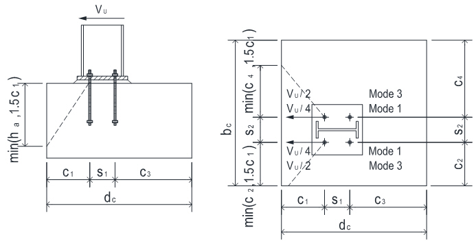
Conc. Shear Breakout Resistance - Perpendicular To Edge |
|
|
|
|
|
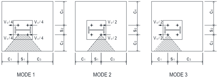
Mode 1 Failure cone at front anchors, strength check against 0.5 x Vu |
|
Mode 3 Failure cone at front anchors, strength check against 1.0 x Vu , applicable when oversized holes are used in base plate |
| |
|
|
|
|
|
|
|
|
|
| |
|
|
|
|
|
|
|
| Bolt edge distance |
c1 |
= |
|
= |
125
|
[mm] |
ACI 318M-11
|
| Limiting ca1 when anchors are influenced by 3 or more edges |
= |
No
|
|
D.6.2.4 |
| Bolt edge distance - adjusted |
c1 |
= |
ca1 needs NOT to be adjusted
|
= |
125
|
[mm] |
D.6.2.4 |
| |
c2 |
= |
|
= |
125
|
[mm] |
|
| |
1.5c1 |
= |
|
= |
188
|
[mm] |
ACI 318M-11
|
| |
Avc |
= |
[min(c2,1.5c1) + s2 + min(c4,1.5c1)]x |
= |
1.2E+05
|
[mm2] |
D.6.2.1 |
| |
|
|
min(1.5c1, ha) |
|
|
|
ACI 318M-11
|
| |
Avco |
= |
4.5c12 |
= |
7.0E+04
|
[mm2] |
D.6.2.1 (D-32) |
| |
Avc |
= |
min ( Avc, n1 Avco ) |
= |
1.2E+05
|
[mm2] |
D.6.2.1 |
| |
le |
= |
min( 8da , hef ) |
= |
203
|
[mm] |
D.6.2.2 |
| |
Vb1 |
= |
|
= |
38.3
|
[kN] |
D.6.2.2 (D-33) |
| |
Vb2 |
= |
|
= |
30.9
|
[kN] |
D.6.2.2 (D-34) |
| |
Vb |
= |
min( Vb1 , Vb2 ) |
= |
30.9
|
[kN] |
D.6.2.2 |
| Eccentricity effects |
Ψec,v |
= |
1.0 shear acts through center of group |
|
|
|
D.6.2.5 |
| Edge effects |
Ψed,v |
= |
min[ (0.7+0.3c2/1.5c1), 1.0 ] |
= |
0.90
|
|
D.6.2.6 |
| Concrete cracking |
Ψc,v |
= |
concrete is cracked
|
= |
1.20
|
|
D.6.2.7 |
| Member thickness |
Ψh,v |
= |
max[ (sqrt(1.5c1 / ha) , 1.0 ] |
= |
1.00
|
|
D.6.2.8 |
| |
|
|
|
|
|
|
ACI 318M-11
|
| Conc shear breakout resistance |
Vcbg |
= |
|
fv,c |
Avc |
Ψec,v Ψed,v Ψc,v Ψh,v Vb |
| Avco |
|
= |
43.8
|
[kN] |
D.6.2.1 (D-31) |
|
Mode 3 is used for checking
|
Vcbg1 |
= |
1.0 x Vcbg
|
= |
43.8
|
[kN] |
|
| |
|
|
|
|
|
|
|
| Mode 2 Failure cone at back anchors |
|
|
|
|
| |
|
|
|
|
|
|
|
|
|
| |
|
|
|
|
|
|
|
| Bolt edge distance |
ca1 |
= |
c1 + s1 |
= |
531
|
[mm] |
ACI 318M-11
|
| Limiting ca1 when anchors are influenced by 3 or more edges |
= |
Yes
|
|
D.6.2.4 |
| Bolt edge distance - adjusted |
ca1 |
= |
ca1 needs to be adjusted
|
= |
253
|
[mm] |
D.6.2.4 |
| |
c2 |
= |
|
= |
125
|
[mm] |
|
| |
1.5ca1 |
= |
|
= |
380
|
[mm] |
ACI 318M-11
|
| |
Avc |
= |
[min(c2,1.5ca1)+ s2 + min(c4,1.5ca1)]x |
= |
2.5E+05
|
[mm2] |
D.6.2.1 |
| |
|
|
min(1.5ca1, ha) |
|
|
|
ACI 318M-11
|
| |
Avco |
= |
4.5ca12 |
= |
2.9E+05
|
[mm2] |
D.6.2.1 (D-32) |
| |
Avc |
= |
min ( Avc, n2 Avco ) |
= |
2.5E+05
|
[mm2] |
D.6.2.1 |
| |
le |
= |
min( 8da , hef ) |
= |
203
|
[mm] |
D.6.2.2 |
| |
Vb1 |
= |
|
= |
110.6
|
[kN] |
D.6.2.2 (D-33) |
| |
Vb2 |
= |
|
= |
89.3
|
[kN] |
D.6.2.2 (D-34) |
| |
Vb |
= |
min( Vb1 , Vb2 ) |
= |
89.3
|
[kN] |
D.6.2.2 |
| Eccentricity effects |
Ψec,v |
= |
1.0 shear acts through center of group |
|
|
|
D.6.2.5 |
| Edge effects |
Ψed,v |
= |
min[ (0.7+0.3c2/1.5ca1), 1.0 ] |
= |
0.80
|
|
D.6.2.6 |
| Concrete cracking |
Ψc,v |
= |
concrete is cracked
|
= |
1.20
|
|
D.6.2.7 |
| Member thickness |
Ψh,v |
= |
max[ (sqrt(1.5ca1 / ha) , 1.0 ] |
= |
1.00
|
|
D.6.2.8 |
| |
|
|
|
|
|
|
ACI 318M-11
|
| Conc shear breakout resistance |
Vcbg2 |
= |
|
fv,c |
Avc |
Ψec,v Ψed,v Ψc,v Ψh,v Vb |
| Avco |
|
= |
55.4
|
[kN] |
D.6.2.1 (D-31) |
| |
|
|
|
|
|
|
|
| Min shear breakout resistance |
fv,cVcbg |
= |
min ( Vcbg1 , Vcbg2 ) |
= |
43.8
|
[kN] |
|
| shear perpendicular to edge |
|
|
|
|
|
|
|
| |
ratio |
= |
0.51
|
>
|
Vu |
OK
|
|
| |
|
|
|
|
|
|
|
| Conc. Shear Breakout Resistance - Parallel To Edge |
|
|
|
|
| |
|
|
|
|
|
|
|
|
|
| |
|
|
|
|
|
|
|
| Mode 1 Shear taken evenly by all anchor bolts, strength check against 0.5 x Vu |
|
| |
|
|
|
|
|
|
|
| Bolt edge distance |
ca1 |
= |
min(c2 , c4) |
= |
125
|
[mm] |
ACI 318M-11
|
| Limiting ca1 when anchors are influenced by 3 or more edges |
= |
No
|
|
D.6.2.4 |
| Bolt edge distance - adjusted |
ca1 |
= |
ca1 needs NOT to be adjusted
|
= |
125
|
[mm] |
D.6.2.4 |
| |
1.5ca1 |
= |
|
= |
188
|
[mm] |
ACI 318M-11
|
| |
Avc |
= |
[min(c1,1.5ca1) + s1+ min(c3,1.5ca1)]x |
= |
1.2E+05
|
[mm2] |
D.6.2.1 |
| |
|
|
min(1.5ca1, ha) |
|
|
|
ACI 318M-11
|
| |
Avco |
= |
4.5ca12 |
= |
7.0E+04
|
[mm2] |
D.6.2.1 (D-32) |
| |
Avc |
= |
min ( Avc, nbd Avco ) |
= |
1.2E+05
|
[mm2] |
D.6.2.1 |
| |
le |
= |
min( 8da , hef ) |
= |
203
|
[mm] |
D.6.2.2 |
| |
Vb1 |
= |
|
= |
38.3
|
[kN] |
D.6.2.2 (D-33) |
| |
Vb2 |
= |
|
= |
30.9
|
[kN] |
D.6.2.2 (D-34) |
| |
Vb |
= |
min( Vb1 , Vb2 ) |
= |
30.9
|
[kN] |
D.6.2.2 |
| Eccentricity effects |
Ψec,v |
= |
1.0 shear acts through center of group |
|
|
|
D.6.2.5 |
| Edge effects |
Ψed,v |
= |
|
= |
1.00 |
|
D.6.2.1 (c) |
| Concrete cracking |
Ψc,v |
= |
concrete is cracked
|
= |
1.20
|
|
D.6.2.7 |
| Member thickness |
Ψh,v |
= |
max[ (sqrt(1.5ca1 / ha) , 1.0 ] |
= |
1.00
|
|
D.6.2.8 |
| |
|
|
|
|
|
|
ACI 318M-11
|
| Conc shear breakout resistance |
Vcbg-p1 |
= |
| 2xfv,c |
Avc |
Ψec,v Ψed,v Ψc,v Ψh,v Vb |
| Avco |
|
= |
97.4
|
[kN] |
D.6.2.1 (D-31) |
| |
|
|
|
|
|
|
D.6.2.1 (c) |
| |
|
|
|
|
|
|
|
| Mode 2 Shear taken evenly by back anchor bolts, strength check against 0.5 x Vu |
|
| |
|
|
|
|
|
|
|
| Bolt edge distance |
ca1 |
= |
min(c2 , c4) |
= |
125
|
[mm] |
ACI 318M-11
|
| Limiting ca1 when anchors are influenced by 3 or more edges |
= |
No
|
|
D.6.2.4 |
| Bolt edge distance - adjusted |
ca1 |
= |
ca1 needs NOT to be adjusted
|
= |
125
|
[mm] |
D.6.2.4 |
| |
1.5ca1 |
= |
|
= |
188
|
[mm] |
ACI 318M-11
|
| |
Avc |
= |
[min(s1+c1,1.5ca1) +min(c3,1.5ca1)]x |
= |
5.9E+04
|
[mm2] |
D.6.2.1 |
| |
|
|
min(1.5ca1, ha) |
|
|
|
ACI 318M-11
|
| |
Avco |
= |
4.5ca12 |
= |
7.0E+04
|
[mm2] |
D.6.2.1 (D-32) |
| |
Avc |
= |
min ( Avc, nbd Avco ) |
= |
5.9E+04
|
[mm2] |
D.6.2.1 |
| |
le |
= |
min( 8da , hef ) |
= |
203
|
[mm] |
D.6.2.2 |
| |
Vb1 |
= |
|
= |
38.3
|
[kN] |
D.6.2.2 (D-33) |
| |
Vb2 |
= |
|
= |
30.9
|
[kN] |
D.6.2.2 (D-34) |
| |
Vb |
= |
min( Vb1 , Vb2 ) |
= |
30.9
|
[kN] |
D.6.2.2 |
| Eccentricity effects |
Ψec,v |
= |
1.0 shear acts through center of group |
|
|
|
D.6.2.5 |
| Edge effects |
Ψed,v |
= |
|
= |
1.00 |
|
D.6.2.1 (c) |
| Concrete cracking |
Ψc,v |
= |
concrete is cracked
|
= |
1.20
|
|
D.6.2.7 |
| Member thickness |
Ψh,v |
= |
max[ (sqrt(1.5ca1 / ha) , 1.0 ] |
= |
1.00
|
|
D.6.2.8 |
| |
|
|
|
|
|
|
ACI 318M-11
|
| Conc shear breakout resistance |
Vcbg-p2 |
= |
| 2xfv,c |
Avc |
Ψec,v Ψed,v Ψc,v Ψh,v Vb |
| Avco |
|
= |
46.4
|
[kN] |
D.6.2.1 (D-31) |
| |
|
|
|
|
|
|
D.6.2.1 (c) |
| |
|
|
|
|
|
|
|
| Mode 3 Shear taken evenly by front anchor bolts, strength check against 0.5 x Vu |
|
| |
|
|
|
|
|
|
|
| Bolt edge distance |
ca1 |
= |
min(c2 , c4) |
= |
125
|
[mm] |
ACI 318M-11
|
| Limiting ca1 when anchors are influenced by 3 or more edges |
= |
No
|
|
D.6.2.4 |
| Bolt edge distance - adjusted |
ca1 |
= |
ca1 needs NOT to be adjusted
|
= |
125
|
[mm] |
D.6.2.4 |
| |
1.5ca1 |
= |
|
= |
188
|
[mm] |
ACI 318M-11
|
| |
Avc |
= |
[min(c1,1.5ca1) + min(s1+c3,1.5ca1)]x |
= |
5.9E+04
|
[mm2] |
D.6.2.1 |
| |
|
|
min(1.5ca1, ha) |
|
|
|
ACI 318M-11
|
| |
Avco |
= |
4.5ca12 |
= |
7.0E+04
|
[mm2] |
D.6.2.1 (D-32) |
| |
Avc |
= |
min ( Avc, nbd Avco ) |
= |
5.9E+04
|
[mm2] |
D.6.2.1 |
| |
le |
= |
min( 8da , hef ) |
= |
203
|
[mm] |
D.6.2.2 |
| |
Vb1 |
= |
|
= |
38.3
|
[kN] |
D.6.2.2 (D-33) |
| |
Vb2 |
= |
|
= |
30.9
|
[kN] |
D.6.2.2 (D-34) |
| |
Vb |
= |
min( Vb1 , Vb2 ) |
= |
30.9
|
[kN] |
D.6.2.2 |
| Eccentricity effects |
Ψec,v |
= |
1.0 shear acts through center of group |
|
|
|
D.6.2.5 |
| Edge effects |
Ψed,v |
= |
|
= |
1.00 |
|
D.6.2.1 (c) |
| Concrete cracking |
Ψc,v |
= |
concrete is cracked
|
= |
1.20
|
|
D.6.2.7 |
| Member thickness |
Ψh,v |
= |
max[ (sqrt(1.5ca1 / ha) , 1.0 ] |
= |
1.00
|
|
D.6.2.8 |
| |
|
|
|
|
|
|
ACI 318M-11
|
| Conc shear breakout resistance |
Vcbg-p3 |
= |
| 2xfv,c |
Avc |
Ψec,v Ψed,v Ψc,v Ψh,v Vb |
| Avco |
|
= |
46.4
|
[kN] |
D.6.2.1 (D-31) |
| |
|
|
|
|
|
|
D.6.2.1 (c) |
| Min shear breakout resistance |
fvcVcbgp |
= |
min(Vcbg-p1 ,Vcbg-p2 , Vcbg-p3 )x2 side |
= |
92.8
|
[kN] |
|
| shear parallel to edge |
|
|
|
|
|
|
|
| |
ratio |
= |
0.24
|
>
|
Vu |
OK
|
|
| |
|
|
|
|
|
|
|
|
Conc. Pryout Shear Resistance
|
|
|
|
|
|
|
ACI 318M-11
|
| |
kcp |
= |
2.0
|
|
|
|
D.6.3.1 |
| Factored shear pryout resistance |
fv,cVcpg |
= |
fv,c kcp Ncbg |
= |
152.3
|
[kN] |
D.6.3.1 (D-41) |
|
|
f v,c
|
= |
0.7 pryout strength is always Condition B |
|
D.4.3 (c) |
| |
|
|
|
|
|
|
|
| Seismic design strength reduction
|
|
=
|
x 0.75 applicable
|
=
|
114.2
|
[kN]
|
D.3.3.4.4
|
|
|
ratio
|
=
|
0.19
|
>
|
Vu |
OK
|
|
|
|
|
|
|
|
|
|
|
|
Govern Shear Resistance
|
Vr
|
=
|
min ( fVsa , fVcbg , fVcbg-p , fVcpg ) |
=
|
43.8
|
[kN]
|
|
|
|
|
|
|
|
|
|
|
|
Tension Shear Interaction
|
|
|
|
|
|
|
ACI 318M-11
|
| Check if Nu >0.2f Nn and Vu
>0.2f Vn
|
=
|
Yes
|
|
|
|
D.7.1 & D.7.2
|
|
|
|
|
Nu / f Nn + Vu / f Vn
|
=
|
0.91
|
|
D.7.3 (D-42)
|
|
|
ratio
|
=
|
0.76
|
<
|
1.2
|
OK
|
|
|
|
|
|
|
|
|
|
|
|
Seismic Design
|
|
|
|
|
|
|
|
|
Tension
|
|
|
Applicable
|
|
|
OK
|
|
| Option D is selected.
|
ACI 318M-11
|
User has to ensure that the tensile load Nu user input above includes
the seismic load E, with E increased
by multiplying overstrength factor Ωo
|
D.3.3.4.3(d)
|
|
|
|
|
|
|
|
|
|
|
|
|
Seismic SDC>=C and E>0.2U , Option D is selected to satisfy additional seismic requirements as per D.3.3.4.3
|
|
|
|
|
|
|
|
|
|
|
|
|
Shear
|
|
|
Applicable
|
|
|
OK
|
|
| Option C is selected.
|
|
|
|
|
|
|
ACI 318M-11
|
User has to ensure that the shear load Vu user input above includes the
seismic load E, with E increased
by multiplying overstrength factor Ωo
|
D.3.3.5.3(c)
|
|
|
|
|
|
|
|
|
|
|
Seismic SDC>=C and E>0.2U , Option C is selected to satisfy additional seismic requirements as per D.3.3.5.3
|
|
|
|
|
|
|
|
|
|
|
|
|
|
|