|
|
|
|
|
|
|
|
|
|
|
|
|
VERTICAL VESSEL CIRCULAR PATTERN ANCHOR BOLT DESIGN
|
|
|
|
Result Summary
|
|
|
|
|
|
|
|
|
|
|
Anchor Rod Embedment, Spacing and Edge Distance
|
|
|
|
Warn
|
|
|
Overall
|
|
|
|
|
ratio
|
=
|
0.73
|
OK
|
|
|
Seismic Design
|
|
|
|
|
Tension
|
=
|
|
NA
|
|
|
|
|
|
|
|
Shear
|
=
|
|
NA
|
|
|
|
Design Code Reference
|
|
|
|
|
|
|
|
|
|
|
Anchor bolt design based on
|
|
|
|
|
|
|
|
|
Code Abbreviation
|
|
ACI 318-11 Building Code Requirements for Structural Concrete and Commentary Appendix D
|
ACI 318-11
|
|
PIP STE03350 Vertical Vessel Foundation Design Guide-2008
|
PIP STE03350
|
|
PIP STE05121 Anchor Bolt Design Guide-2006
|
PIP STE05121
|
|
ASCE Anchorage Design for Petrochemical Facilities-2013
|
ASCE Anchorage
|
|
|
|
|
|
|
|
|
|
|
Code Reference
|
|
Design Option
|
|
|
|
|
|
|
Select anchor bolt design code
|
|
|
|
|
|
|
|
Select design using or not
using anchor reinforcement
|
|
|
|
|
|
|
|
Concrete Mat or Pedestal Input
|
|
|
|
|
|
|
|
|
Dp=159.36
Sp=66.01
Dbc=144.00
c1=7.68
c2=19.29
c4=19.29
ANC
|
|
|
|
|
Select concrete mat shape
|
|
=
|
|
|
|
|
|
|
Octagon mat face-to-face distance
|
Dp
|
=
|
|
[in]
|
|
|
|
|
|
|
No of anchor bolt
|
Nab
|
=
|
|
|
|
|
|
|
Anchor bolt bolt circle diameter
|
Dbc
|
=
|
|
[in]
|
|
|
|
|
|
|
Anchor Bolt Forces Input
|
|
|
|
|
|
|
|
|
|
|
|
Anchor bolt loads input by
|
|
=
|
|
|
Factored moment at base of vessel
|
Mu
|
=
|
|
[kip-ft]
|
|
|
|
|
|
|
|
Factored shear at base of vessel
|
Vu
|
=
|
|
[kips]
|
|
|
|
|
|
|
|
Empty vessel weight
|
De
|
=
|
|
[kips]
|
|
|
|
|
|
|
Anchor Bolt Data Input
|
|
|
|
|
|
|
|
|
Concrete strength
|
f'c
|
=
|
|
[ksi]
|
Error: the conc strength shall be 2~10 ksi
|
|
|
|
Anchor bolt material
|
|
=
|
|
|
|
|
|
|
|
Anchor tensile strength
|
futa
|
=
|
58.0
|
[ksi]
|
|
|
|
|
ACI 318-11
|
|
|
|
|
Anchor is ductile steel element
|
|
|
|
D.1
|
|
Anchor bolt diameter
|
da
|
=
|
|
[in]
|
|
|
|
|
|
|
Anchor bolt has sleeve
|
|
=
|
|
|
|
|
|
|
|
|
Anchor bolt head type
|
|
=
|
|
|
|
|
|
|
Anchor effective cross section area
|
Ase
|
=
|
1.410
|
[in2]
|
|
|
|
|
|
Anchor bolt head bearing area
|
Abrg
|
=
|
|
[in2]
|
|
|
|
|
Anchor bolt 1/8" (3mm) corrosion allowance
|
=
|
|
|
|
|
|
|
|
|
|
|
|
|
|
|
|
|
|
PIP STE05121
|
|
Anchor bolt embedment depth
|
hef
|
=
|
|
[in]
|
18.00
|
|
Warn
|
|
Page A -1 Table 1
|
|
Pedestal height
|
ha
|
=
|
|
[in]
|
17.50
|
|
OK
|
|
|
|
Supplementary reinforcement
|
|
|
|
|
|
|
|
|
ACI 318-11
|
|
For tension
|
|
=
|
|
Condition B
|
|
|
|
D.4.3 (c)
|
|
For shear
|
Yc,v
|
=
|
|
Condition A
|
|
|
|
D.6.2.7
|
|
|
|
Concrete cracking
|
|
=
|
|
|
|
|
|
D.5.2.6, D5.3.6, D.6.2.7
|
|
|
|
Provide built-up grout pad ?
|
|
=
|
|
|
|
|
|
|
D.6.1.3
|
|
Seismic Input
|
|
|
|
|
|
|
|
|
ACI 318-11
|
|
Seismic design category SDC >= C
|
|
=
|
|
|
|
|
|
|
D.3.3.1
|
|
|
Design Basis and Assumptions
|
|
|
The design of circular pattern anchor bolt group uses the Method
2 Sawcut with hef’ and Neutral Axis at Center as stated in
the following references
1. ASCE Anchorage Design for Petrochemical Facilities - 2013 Example
2 Step 5(c) on Page 145
2. ASCE 2010 Structural Congress - Concrete Breakout Strength in Tension for Vertical
Vessel Anchorage in Octagon Pedestals
The design of circular pattern anchor bolt group is simplified as design of a single
anchor bolt with 3 side free edges sawcut at midway between adjacent anchors. The
simplified design method uses the following assumptions
1. The moment is resisted only by the anchor bolt group and it does not take into
account the contribution of concrete compression
force against base plate in the moment equilibrium
2. The neutral axis is not shifted and is located at center of vessel
3. It does not consider strain compatibility between the concrete and steel elements
which comprise the anchorage.
4. In the assumed 3 side free edges sawcut model, when anchor is located less than
1.5hef from three or more edges, the reduced
hef' is used to calculate concrete projected failure
area ANC
The utilization ratio of simplified method used in this calculation is conservative
compared to the accurate but more complex approach. The detail comparison and analysis
of this simplified method is addressed in reference 2 above.
|
|
|
|
|
CONCLUSION
|
|
|
|
|
|
|
|
|
View Detail Calc
|
|
Anchor Rod Embedment, Spacing and Edge Distance
|
|
|
|
Warn
|
|
|
Overall
|
ratio
|
=
|
0.73
|
OK
|
|
|
Tension
|
|
|
|
|
|
|
Anchor Rod Tensile Resistance
|
ratio
|
=
|
0.48
|
OK
|
|
|
Concrete Tensile Breakout Resistance
|
ratio
|
=
|
0.73
|
OK
|
|
|
Anchor Pullout Resistance
|
ratio
|
=
|
0.23
|
OK
|
|
|
Side Blowout Resistance
|
ratio
|
=
|
0.00
|
NA
|
|
|
Shear
|
|
|
|
|
|
|
Anchor Rod Shear Resistance
|
ratio
|
=
|
0.00
|
OK
|
|
|
Concrete Shear Breakout Resistance - Perpendicular To Edge
|
ratio
|
=
|
0.00
|
OK
|
|
|
Concrete Shear Breakout Resistance - Parallel To Edge
|
ratio
|
=
|
0.00
|
OK
|
|
|
Concrete Pryout Shear Resistance
|
ratio
|
=
|
0.00
|
OK
|
|
|
Tension Shear Interaction
|
|
|
|
|
|
|
Tension Shear Interaction
|
ratio
|
=
|
0.00
|
OK
|
|
|
|
|
|
|
|
|
|
Seismic Design
|
|
|
|
|
ACI 318-11
|
|
Tension
|
Not Applicable
|
|
|
|
NA
|
D.3.3.4
|
|
Seismic SDC< C or E<=0.2U , additional seismic requirements in D.3.3.4.3 is NOT required, as per D.3.3.1 & D.3.3.4.1
|
|
|
|
|
|
|
|
|
|
|
|
|
|
|
Shear
|
Not Applicable
|
|
|
|
NA
|
D.3.3.5
|
|
Seismic SDC< C or E<=0.2U , additional seismic requirements in D.3.3.5.3 is NOT required, as per D.3.3.1 & D.3.3.5.1
|
|
|
|
|
CACULATION
|
|
|
|
|
|
|
|
|
|
|
|
Single Anchor Bolt Tensile and Shear Load
|
|
|
|
PIP STE03350
|
|
Factored compression at top of concrete pedestal
|
Pu
|
=
|
Mu /0.667 Dbc + 0.9 De /2
|
=
|
210.10
|
[kips]
|
Section 4.6.2 Eq 5
|
|
Factored frictional resistance
|
f Vf
|
=
|
f m Pu = 0.75 x 0.55 x Pu
|
=
|
86.67
|
[kips]
|
Section 4.6.2 Eq 6
|
|
|
|
>
|
Vu
|
shear load taken by the friction
|
Section 4.6.2 Eq 7
|
|
Factored single bolt tensile load
|
Nua
|
=
|
4 Mu / (Nab x Dbc) - 0.9 De / Nab
|
=
|
29.54
|
[kips]
|
Section 4.6.1 Eq 4
|
|
Factored single bolt shear load
|
Vua
|
=
|
shear load taken by the friction
|
=
|
0.00
|
[kips]
|
|
|
|
|
|
Single Anchor Bolt Edge Distances and Projected Failure Area
|
|
|
|
|
|
Anchor bolt edge distance
|
c1
|
=
|
(Dp - Dbc) / 2
|
=
|
7.68
|
[in]
|
|
|
|
c3
|
=
|
Dp - c1
|
=
|
151.68
|
[in]
|
|
|
|
c2
|
=
|
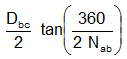
|
=
|
19.29
|
[in]
|
|
|
|
c4
|
=
|
c2
|
|
|
=
|
19.29
|
[in]
|
ACI 318-11
|
|
Effective embedment depth
|
hef'
|
=
|
|
=
|
12.86
|
[in]
|
D.5.2.3
|
|
Octagon side edge length
|
Sp
|
=
|
Dp / (1+√2)
|
=
|
66.01
|
[in]
|
|
|
Octagon shape conc mat area
|
Ap
|
=
|
|
=
|
21038
|
[in2]
|
|
|
Projected conc failure area
|
ANC
|
=
|
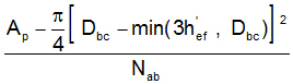
|
=
|
1026
|
[in2]
|
|
|
|
|
|
|
|
|
|
|
|
|
|
|
|