

Verify AISC DG4 Bolt No Prying Assumption
AISC DG4 Is Used
Bolt Moment Strength (No Prying)
bolt grade
= A325-N
Ft
= 90.0
[ksi]
AISC 14th Table J3.2
bolt dia db
= 1.250
[in]
bolt area Ab
= 1.227
[in2]
Bolt norminal tensile strength
Pt
= Ft Ab
= 110.45
[kips]
AISC 14th Eq J3-1
Tension bolt moment arm
h0
= 26.043
[in]
h1
= 20.571
[in]
h2
= 17.225
[in]
h3
= 13.879
[in]
The
following bolt moment without prying action for 12 bolts MRE 1/3-4W/2W
bolt pattern is taken from Table 3-12 in Virginia Tech Report to MBMA,
Developing and Validating New Bolted End-Plate Moment Connection
Configurations July 2015 by Nonish Jain, Matthew Eatherton and Thomas
Murray. Thomas Murray is the author of both AISC DG4 and DG16.
Bolt moment strength (no prying)
Mnp
= 2 Pt ( 2 h0 + 2 h1 + h2 + h3 )
= 2288.68
[kip-ft]
Bolt resistance factor-LRFD
φ
= 0.75
AISC 14th Eq J3-1
φ Mnp
=
= 1716.51
[kip-ft]
End Plate Bending Strength
End plate width
bplate
= 16.535
[in]
thickness tp
= 2.000
[in]
Beam flange width
bfb
= 12.756
[in]
Effective end plate width
bp
= min ( bplate , bfb + 1" )
= 13.756
[in]
AISC DG4 Page 9 item 5
End plate yield strength
Fyp
= 50.0
[ksi]
The
following end plate yield line for 12 bolts MRE 1/3-4W/2W bolt pattern
is taken from Table 3-12 in Virginia Tech Report to MBMA, Developing and
Validating New Bolted End-Plate Moment Connection Configurations July
2015 by Nonish Jain, Matthew Eatherton and Thomas Murray. Thomas Murray
is the author of both AISC DG4 and DG16.
formulas for calculating yield-line parameters
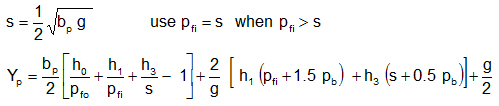
Tension bolt moment arm
h0
= 26.043
[in]
h1
= 20.571
[in]
h2
= 17.225
[in]
h3
= 13.879
[in]
g
= 5.118
[in]
pb
= 3.346
[in]
pfi
= 2.362
[in]
pfo
= 2.362
[in]
s
= 4.195
[in]
Yp
= 245.33
[in]
Flexure resistance factor-LRFD
φb
= 0.90
AISC 14th F1 (1)
End plate bending strength
φb Mpl
= φb Fyp t2 p Yp
= 3680.00
[kip-ft]
Check thick end plate condition
φb Mpl >= 1.11 X φ Mnp
AISC DG4 Eq 3.33
ratio
= 0.52 thick plate
Column Flange Bending Strength
The
column flange yield line for MRE 1/3 bolt pattern is taken from Table
8.13 of Virginia Tech Emmet Sumner's PhD thesis - Unified Design of
Extended End-Plate Moment Connections Subject to Cyclic Loading June,
2003. This thesis was approved by Thomas M. Murray who is the author of
AISC DG4 and DG16.
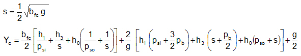
formulas for calculating yield-line parameters
Tension bolt moment arm
h0
= 26.043
[in]
h1
= 20.571
[in]
h2
= 17.225
[in]
h3
= 13.879
[in]
*** Stiffened Column Flange Case ***
Column section
bfc
= 19.685
[in]
tfc
= 1.575
[in]
Fyc
= 50.0
[ksi]
g
= 5.118
[in]
s
= 5.019
[in]
c
= 5.472
[in]
Stiffener plate thickness
ts
= 0.500
[in]
psi
= 2.486
[in]
pso
= 2.486
[in]
pb
= 3.346
[in]
Yc
= 438.4
[in]
Flexure resistance factor-LRFD
φb
= 0.90
AISC 14th F1 (1)
Column flange bending strength
φb Mcf
= φb Fyc t2 fc Yc
= 4078.19
[kip-ft]
Check thick column flange condition
φb Mcf >= 1.11 X φ Mnp
AISC DG4 Eq 3.35
ratio
= 0.47 thick plate
The thick end plate and column flange conditions are met. AISG DG4 is used and
no bolt prying is considered
no bolt prying is considered
AISC DG4 Eq 3.33 & 3.35