


Seismic - SCBF LC1 & LC2 Gusset Interface Forces Calc
Brace - SCBF Load Case LC1
Top and bottom brace force
Top Ptop
= -559.7
[kips] (T)
Bot Pbot
= 524.4
[kips] (C)
Beam end shear & transfer force
Shear Rb
= 19.9
[kips]
Transfer Ab
= -46.3
[kips]
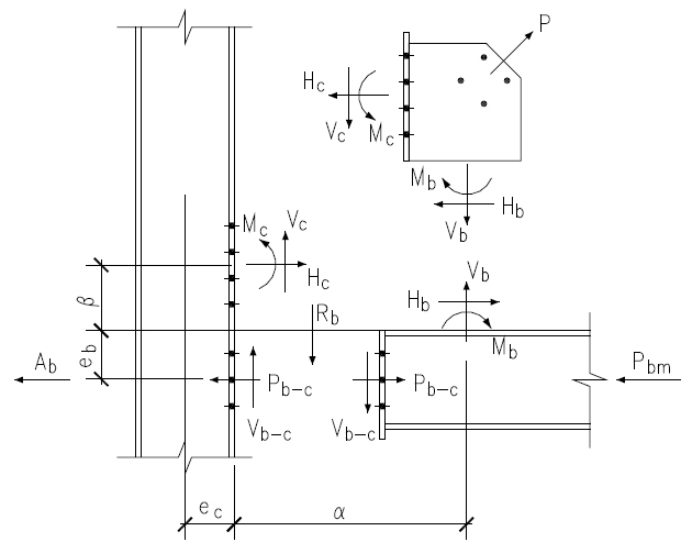
Top Brace Interface Forces
Refer to AISC 15th Page 13-4 and Fig. 13-2 for all charts and definitions of variables and symbols shown in calculation below
eb
= 12.350
[in]
ec
= 6.450
[in]
α
= 14.000
[in]
β
= 9.625
[in]
θ
= 45.0
[°]
K
= eb tanθ - ec
= 5.900
[in]
AISC 15th Eq. 13-16
D
= tan2 θ + (2
αβ
) = 3.116
AISC 15th Eq. 13-24
K'
= α ( tan θ +
αβ
) = 34.364
AISC 15th Eq. 13-23
α
= [ K' tan θ + K (2 ] / D
αβ
) = 14.000
[in]
AISC 15th Eq. 13-21
β
= ( K' - K tan θ ) / D
= 8.100
[in]
AISC 15th Eq. 13-22
r
= [ ( eb + β ) 2 + ( ec + α ) 2 ]0.5
= 28.921
[in]
AISC 15th Eq. 13-6
Brace axial force
Pu
= from seismic brace force calc
= -559.7
[kips]
in tension
Gusset to Column Interface Forces
Shear force
Vc
= ( β / r ) Pu
= -156.8
[kips]
AISC 15th Eq. 13-2
Axial force
Hc
= ( ec / r ) Pu
= -124.8
[kips]
AISC 15th Eq. 13-3
Moment
Mc
= Hc ( β - β )
= 15.86
[kip-ft]
AISC 15th Eq. 13-19
Gusset to Beam Interface Forces
Shear force
Hb
= ( α / r ) Pu
= -270.9
[kips]
AISC 15th Eq. 13-5
Axial force
Vb
= ( eb / r ) Pu
= -239.0
[kips]
AISC 15th Eq. 13-4
Moment
Mb
= Vb ( α - α )
= 0.00
[kip-ft]
AISC 15th Eq. 13-17
Bottom Brace Interface Forces
Refer to AISC 15th Page 13-4 and Fig. 13-2 for all charts and definitions of variables and symbols shown in calculation below
eb
= 12.350
[in]
ec
= 6.450
[in]
α
= 14.750
[in]
β
= 10.375
[in]
θ
= 45.0
[°]
K
= eb tanθ - ec
= 5.900
[in]
AISC 15th Eq. 13-16
D
= tan2 θ + (2
αβ
) = 3.021
AISC 15th Eq. 13-24
K'
= α ( tan θ +
αβ
) = 35.720
AISC 15th Eq. 13-23
α
= [ K' tan θ + K (2 ] / D
αβ
) = 14.750
[in]
AISC 15th Eq. 13-21
β
= ( K' - K tan θ ) / D
= 8.850
[in]
AISC 15th Eq. 13-22
r
= [ ( eb + β ) 2 + ( ec + α ) 2 ]0.5
= 29.981
[in]
AISC 15th Eq. 13-6
Brace axial force
Pu
= from seismic brace force calc
= 524.4
[kips]
in compression
Gusset to Column Interface Forces
Shear force
Vc
= ( β / r ) Pu
= 154.8
[kips]
AISC 15th Eq. 13-2
Axial force
Hc
= ( ec / r ) Pu
= 112.8
[kips]
AISC 15th Eq. 13-3
Moment
Mc
= Hc ( β - β )
= -14.34
[kip-ft]
AISC 15th Eq. 13-19
Gusset to Beam Interface Forces
Shear force
Hb
= ( α / r ) Pu
= 258.0
[kips]
AISC 15th Eq. 13-5
Axial force
Vb
= ( eb / r ) Pu
= 216.0
[kips]
AISC 15th Eq. 13-4
Moment
Mb
= Vb ( α - α )
= 0.00
[kip-ft]
AISC 15th Eq. 13-17
Beam to Column Interface Forces
Beam to Column Interface Shear Force
Beam end shear reaction
Rb
= from user input
= 19.9
[kips]
Top brace gusset-beam axial force
Vb-top
=
= -239.0
[kips]
AISC 15th Eq. 13-4
Bot brace gusset-beam axial force
Vb-bot
=
= 216.0
[kips]
AISC 15th Eq. 13-4
Beam to column shear force
Vb-c
= Rb + Vb-top - Vb-bot
= -435.1
[kips]
AISC 15th Page 13-4
Beam to Column Interface Axial Force
Top brace gusset-column axial force
Hc-top
=
= -124.8
[kips]
AISC 15th Eq. 13-3
Bot brace gusset-column axial force
Hc-bot
=
= 112.8
[kips]
AISC 15th Eq. 13-3
Transfer force from adjacent bay
Ab
= from user input
= -46.3
[kips]
Beam to column axial force
Pb-c
= ( Hc-top + Hc-bot ) x -1 - Ab
= 58.3
[kips]
AISC 15th Page 13-4
Beam Member Axial Force
This force is not for use in connection calc. It's output here for user input connection forces equilibrium check only.
Pbm - Beam member axial force is different from Pb-c - Beam to column interface axial force as shown above.
Pbm - Beam member axial force
is from structural analysis output and cannot be used directly in beam
end to column connection design as this force is interrupted by brace
gusset to beam interface force before beam end reaching the column. This
force is actually not needed from user's input for beam end to column
connection design.
Pb-c - Beam to column interface axial force
is calculated from user's input of brace axial forces and trasnfer
force using uniform force method. This force is used in the beam end to
column connection design.
Pbm - Beam member axial force
is not needed for the beam end to column connection design and is
calculated here for verification purpose only. If it matches the
structural analysis output, that means equilibrium is reached and user's
input of brace axial forces and trasnfer force are correct.
Top brace axial force
Pt
= from seismic brace force calc
= -559.7
[kips]
in tension
Top brace to ver line angle
θt
= from user input
= 45.0
[°]
Top brace gusset-column axial force
Hct
= from calc shown above
= -124.8
[kips]
AISC 15th Eq. 13-3
Bot brace axial force
Pb
= from seismic brace force calc
= 524.4
[kips]
in compression
Bot brace to ver line angle
θb
= from user input
= 45.0
[°]
Bot brace gusset-column axial force
Hcb
= from calc shown above
= 112.8
[kips]
AISC 15th Eq. 13-3
Beam to column interface axial force
Pb-c
= from calc shown above
= 58.3
[kips]
AISC 15th Page 13-4
Beam member axial force
Pbm
= (Hct - Pt sinθt ) + (Hcb - Pb sinθb )
= 71.3
[kips]
in compression
+ Pb-c
Brace - SCBF Load Case LC2
Top and bottom brace force
Top Ptop
= 449.1
[kips] (C)
Bot Pbot
= -615.9
[kips] (T)
Beam end shear & transfer force
Shear Rb
= 19.9
[kips]
Transfer Ab
= -46.3
[kips]
Top Brace Interface Forces
Refer to AISC 15th Page 13-4 and Fig. 13-2 for all charts and definitions of variables and symbols shown in calculation below
eb
= 12.350
[in]
ec
= 6.450
[in]
α
= 14.000
[in]
β
= 9.625
[in]
θ
= 45.0
[°]
K
= eb tanθ - ec
= 5.900
[in]
AISC 15th Eq. 13-16
D
= tan2 θ + (2
αβ
) = 3.116
AISC 15th Eq. 13-24
K'
= α ( tan θ +
αβ
) = 34.364
AISC 15th Eq. 13-23
α
= [ K' tan θ + K (2 ] / D
αβ
) = 14.000
[in]
AISC 15th Eq. 13-21
β
= ( K' - K tan θ ) / D
= 8.100
[in]
AISC 15th Eq. 13-22
r
= [ ( eb + β ) 2 + ( ec + α ) 2 ]0.5
= 28.921
[in]
AISC 15th Eq. 13-6
Brace axial force
Pu
= from seismic brace force calc
= 449.1
[kips]
in compression
Gusset to Column Interface Forces
Shear force
Vc
= ( β / r ) Pu
= 125.8
[kips]
AISC 15th Eq. 13-2
Axial force
Hc
= ( ec / r ) Pu
= 100.2
[kips]
AISC 15th Eq. 13-3
Moment
Mc
= Hc ( β - β )
= -12.73
[kip-ft]
AISC 15th Eq. 13-19
Gusset to Beam Interface Forces
Shear force
Hb
= ( α / r ) Pu
= 217.4
[kips]
AISC 15th Eq. 13-5
Axial force
Vb
= ( eb / r ) Pu
= 191.8
[kips]
AISC 15th Eq. 13-4
Moment
Mb
= Vb ( α - α )
= 0.00
[kip-ft]
AISC 15th Eq. 13-17
Bottom Brace Interface Forces
Refer to AISC 15th Page 13-4 and Fig. 13-2 for all charts and definitions of variables and symbols shown in calculation below
eb
= 12.350
[in]
ec
= 6.450
[in]
α
= 14.750
[in]
β
= 10.375
[in]
θ
= 45.0
[°]
K
= eb tanθ - ec
= 5.900
[in]
AISC 15th Eq. 13-16
D
= tan2 θ + (2
αβ
) = 3.021
AISC 15th Eq. 13-24
K'
= α ( tan θ +
αβ
) = 35.720
AISC 15th Eq. 13-23
α
= [ K' tan θ + K (2 ] / D
αβ
) = 14.750
[in]
AISC 15th Eq. 13-21
β
= ( K' - K tan θ ) / D
= 8.850
[in]
AISC 15th Eq. 13-22
r
= [ ( eb + β ) 2 + ( ec + α ) 2 ]0.5
= 29.981
[in]
AISC 15th Eq. 13-6
Brace axial force
Pu
= from seismic brace force calc
= -615.9
[kips]
in tension
Gusset to Column Interface Forces
Shear force
Vc
= ( β / r ) Pu
= -181.8
[kips]
AISC 15th Eq. 13-2
Axial force
Hc
= ( ec / r ) Pu
= -132.5
[kips]
AISC 15th Eq. 13-3
Moment
Mc
= Hc ( β - β )
= 16.84
[kip-ft]
AISC 15th Eq. 13-19
Gusset to Beam Interface Forces
Shear force
Hb
= ( α / r ) Pu
= -303.0
[kips]
AISC 15th Eq. 13-5
Axial force
Vb
= ( eb / r ) Pu
= -253.7
[kips]
AISC 15th Eq. 13-4
Moment
Mb
= Vb ( α - α )
= 0.00
[kip-ft]
AISC 15th Eq. 13-17
Beam to Column Interface Forces
Beam to Column Interface Shear Force
Beam end shear reaction
Rb
= from user input
= 19.9
[kips]
Top brace gusset-beam axial force
Vb-top
=
= 191.8
[kips]
AISC 15th Eq. 13-4
Bot brace gusset-beam axial force
Vb-bot
=
= -253.7
[kips]
AISC 15th Eq. 13-4
Beam to column shear force
Vb-c
= Rb + Vb-top - Vb-bot
= 465.4
[kips]
AISC 15th Page 13-4
Beam to Column Interface Axial Force
Top brace gusset-column axial force
Hc-top
=
= 100.2
[kips]
AISC 15th Eq. 13-3
Bot brace gusset-column axial force
Hc-bot
=
= -132.5
[kips]
AISC 15th Eq. 13-3
Transfer force from adjacent bay
Ab
= from user input
= -46.3
[kips]
Beam to column axial force
Pb-c
= ( Hc-top + Hc-bot ) x -1 - Ab
= 78.6
[kips]
AISC 15th Page 13-4
Beam Member Axial Force
This force is not for use in connection calc. It's output here for user input connection forces equilibrium check only.
Pbm - Beam member axial force is different from Pb-c - Beam to column interface axial force as shown above.
Pbm - Beam member axial force
is from structural analysis output and cannot be used directly in beam
end to column connection design as this force is interrupted by brace
gusset to beam interface force before beam end reaching the column. This
force is actually not needed from user's input for beam end to column
connection design.
Pb-c - Beam to column interface axial force
is calculated from user's input of brace axial forces and trasnfer
force using uniform force method. This force is used in the beam end to
column connection design.
Pbm - Beam member axial force
is not needed for the beam end to column connection design and is
calculated here for verification purpose only. If it matches the
structural analysis output, that means equilibrium is reached and user's
input of brace axial forces and trasnfer force are correct.
Top brace axial force
Pt
= from seismic brace force calc
= 449.1
[kips]
in compression
Top brace to ver line angle
θt
= from user input
= 45.0
[°]
Top brace gusset-column axial force
Hct
= from calc shown above
= 100.2
[kips]
AISC 15th Eq. 13-3
Bot brace axial force
Pb
= from seismic brace force calc
= -615.9
[kips]
in tension
Bot brace to ver line angle
θb
= from user input
= 45.0
[°]
Bot brace gusset-column axial force
Hcb
= from calc shown above
= -132.5
[kips]
AISC 15th Eq. 13-3
Beam to column interface axial force
Pb-c
= from calc shown above
= 78.6
[kips]
AISC 15th Page 13-4
Beam member axial force
Pbm
= (Hct - Pt sinθt ) + (Hcb - Pb sinθb )
= 71.6
[kips]
in compression
+ Pb-c