Result Summary - Overall
Horizontal Brace Connection
Code=AISC 360-10 LRFD

 
Result Summary - Overall
geometries & weld limitations = PASS
limit states max ratio 
0.85
PASS
 
Brace to Gusset
geometries & weld limitations = PASS
limit states max ratio 
0.35
PASS
 
Gusset to Ver Beam
geometries & weld limitations = PASS
limit states max ratio 
0.85
PASS
 
Gusset to Hor Beam
geometries & weld limitations = PASS
limit states max ratio 
0.85
PASS


Sketch
Horizontal Brace Connection
Code=AISC 360-10 LRFD


Members & Components Summary

Member
Brace Connection
Code=AISC 360-10 LRFD

 
Hor Beam Section


W12X45
d
 = 12.100
[in]
bf
 = 8.050
[in]

tf
 = 0.575
[in]
tw
 = 0.335
[in]

kdes
 = 1.080
[in]
kdet
 = 1.375
[in]

k1
 = 0.938
[in]
A
 = 13.100
[in2]

 
Sx
 = 57.70
[in3]
Zx
 = 64.20
[in3]

 
Steel Grade A992
Fy
 = 50.0
[ksi]
Fu
 = 65.0
[ksi]

 
Ver Beam Section


W12X40
d
 = 11.900
[in]
bf
 = 8.010
[in]

tf
 = 0.515
[in]
tw
 = 0.295
[in]

kdes
 = 1.020
[in]
kdet
 = 1.375
[in]

k1
 = 0.875
[in]
A
 = 11.700
[in2]

 
Sx
 = 51.50
[in3]
Zx
 = 57.00
[in3]

 
Steel Grade A992
Fy
 = 50.0
[ksi]
Fu
 = 65.0
[ksi]


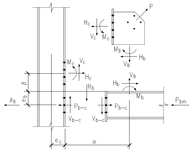
Gusset Plate Interface Forces Calculation


Brace Axial Force Load Case 1


Brace force
P
 = -25.00
[kips] (T)

Beam end shear & transfer force
Shear Rb
 = 25.00
[kips]
Transfer Ab
 = 15.00
[kips]


Refer to AISC 14th  Page 13-4 and Fig. 13-2 for all charts and definitions of variables and symbols shown in calculation below
eb
 = 0.168
[in]
ec
 = 0.148
[in]

α
 = 10.483
[in]
β
 = 13.783
[in]

θ
 = 45.0
[°]

K
 = eb tanθ - ec
 = 0.020
[in]
AISC 14th  Eq. 13-16
D
 = tan2 θ + (
α/β
)2
 = 1.578
AISC 14th  Eq. 13-24
K'
 = α ( tan θ +
α/β
)
 = 18.455
AISC 14th  Eq. 13-23
α
 = [ K' tan θ + K (
α/β
)2 ] / D
 = 11.699
[in]
AISC 14th  Eq. 13-21
β
 = ( K' - K tan θ ) / D
 = 11.679
[in]
AISC 14th  Eq. 13-22
r
 = [ ( eb + β ) 2 + ( ec + α ) 2 ]0.5
 = 16.754
[in]
AISC 14th  Eq. 13-6


Brace axial force
Pu
 = from user input
 = -25.00
[kips]
in tension
Gusset to Ver Beam Interface Forces

Shear force
Vc
 = ( β / r ) Pu
 = -17.43
[kips]
AISC 14th  Eq. 13-2
Axial force
Hc
 = ( ec / r ) Pu
 = -0.22
[kips]
AISC 14th  Eq. 13-3
Moment
Mc
 = Hc ( β - β )
 = 0.04
[kip-ft]
AISC 14th  Eq. 13-19
Gusset to Hor Beam Interface Forces

Shear force
Hb
 = ( α / r ) Pu
 = -17.46
[kips]
AISC 14th  Eq. 13-5
Axial force
Vb
 = ( eb / r ) Pu
 = -0.25
[kips]
AISC 14th  Eq. 13-4
Moment
Mb
 = Vb ( α - α )
 = -0.03
[kip-ft]
AISC 14th  Eq. 13-17


Brace Axial Force Load Case 2


Brace force
P
 = 25.00
[kips] (C)

Beam end shear & transfer force
Shear Rb
 = 25.00
[kips]
Transfer Ab
 = 15.00
[kips]


Refer to AISC 14th  Page 13-4 and Fig. 13-2 for all charts and definitions of variables and symbols shown in calculation below
eb
 = 0.168
[in]
ec
 = 0.148
[in]

α
 = 10.483
[in]
β
 = 13.783
[in]

θ
 = 45.0
[°]

K
 = eb tanθ - ec
 = 0.020
[in]
AISC 14th  Eq. 13-16
D
 = tan2 θ + (
α/β
)2
 = 1.578
AISC 14th  Eq. 13-24
K'
 = α ( tan θ +
α/β
)
 = 18.455
AISC 14th  Eq. 13-23
α
 = [ K' tan θ + K (
α/β
)2 ] / D
 = 11.699
[in]
AISC 14th  Eq. 13-21
β
 = ( K' - K tan θ ) / D
 = 11.679
[in]
AISC 14th  Eq. 13-22
r
 = [ ( eb + β ) 2 + ( ec + α ) 2 ]0.5
 = 16.754
[in]
AISC 14th  Eq. 13-6


Brace axial force
Pu
 = from user input
 = 25.00
[kips]
in compression
Gusset to Ver Beam Interface Forces

Shear force
Vc
 = ( β / r ) Pu
 = 17.43
[kips]
AISC 14th  Eq. 13-2
Axial force
Hc
 = ( ec / r ) Pu
 = 0.22
[kips]
AISC 14th  Eq. 13-3
Moment
Mc
 = Hc ( β - β )
 = -0.04
[kip-ft]
AISC 14th  Eq. 13-19
Gusset to Hor Beam Interface Forces

Shear force
Hb
 = ( α / r ) Pu
 = 17.46
[kips]
AISC 14th  Eq. 13-5
Axial force
Vb
 = ( eb / r ) Pu
 = 0.25
[kips]
AISC 14th  Eq. 13-4
Moment
Mb
 = Vb ( α - α )
 = 0.03
[kip-ft]
AISC 14th  Eq. 13-17


Top Brace - Brace to Gusset
Sect=WT4X12
PLC1 =-25.00 kips (T)
PLC2 =25.00 kips (C)
Code=AISC 360-10 LRFD

 
Result Summary
geometries & weld limitations = PASS
limit states max ratio 
0.35
PASS
 
 
Geometry Restriction Checks - WT Flange to Gusset
PASS
Min Bolt Edge Distance - WT Flange to Gusset


Bolt diameter
db
 = 
 = 0.750
[in]

Min edge distance allowed
Le-min
 = 
 = 1.000
[in]
AISC 14th  Table J3.4
Min edge distance in WT Flange to Gusset
Le
 = 
 = 1.250
[in]

 > Le-min
OK
Min Bolt Spacing - WT Flange to Gusset


Bolt diameter
db
 = 
 = 0.750
[in]

Min bolt spacing allowed
Ls-min
 = 2.667 db
 = 2.000
[in]
AISC 14th  J3.3
Min Bolt spacing in WT Flange to Gusset
Ls
 = 
 = 3.000
[in]

 > Ls-min
OK


Brace Force Load Case 1
Sect=WT4X12
P =-25.00 kips (T)
ratio = 0.35
PASS

WT Shape Brace - Tensile Yield
ratio = 25.00 / 159.30
0.16
PASS
Gross area subject to tension
Ag
 = 
 = 3.540
[in2]

Steel yield strength
Fy
 = 
 = 50.0
[ksi]

Tensile force required
Pu
 = 
 = 25.00
[kips]

Tensile yielding strength
Rn
 = Fy Ag
 = 177.00
[kips]
AISC 14th  Eq D2-1
Resistance factor-LRFD
φ
 = 0.90
AISC 14th  D2 (a)
φ Rn
 = 
 = 159.30
[kips]
AISC 14th  Eq D2-1
ratio
 = 0.16
 > Pu
OK
 
WT Shape Brace - Tensile Rupture
ratio = 25.00 / 106.38
0.24
PASS
Section gross area
Ag
 = WT4X12
 = 3.540
[in2]

Bolt hole diameter
bolt dia db
 = 34
[in]
bolt hole dia dh
 = 78
[in]
AISC 14th  B4.3b
Number of bolt row
nv
 = 2
flange tf
 = 0.400
[in]

Tensile net area
An
 = Ag - nv dh tf
 = 2.840
[in2]


No of bolt column
nh
 = 2
bolt space sh
 = 3.000
[in]

Length of connection
L
 = ( nh -1 ) sh
 = 3.000
[in]

Eccentricity of connection
x
 = from sect WT4X12
 = 0.695
[in]

Shear lag factor
U
 = 1 - x / L
 = 0.768
AISC 14th  Table D3.1


Tensile force required
Pu
 = 
 = 25.00
[kips]

Tensile effective net area
Ae
 = An U
 = 2.182
[in2]

Plate tensile strength
Fu
 = 
 = 65.0
[ksi]

Tensile rupture strength
Rn
 = Fu Ae
 = 141.83
[kips]
AISC 14th  Eq D2-2
Resistance factor-LRFD
φ
 = 0.75
AISC 14th  D2 (b)
φ Rn
 = 
 = 106.38
[kips]
AISC 14th  Eq D2-2
ratio
 = 0.24
 > Pu
OK
 
 
WT Brace - Bolt Shear
ratio = 25.00 / 71.57
0.35
PASS
Bolt shear stress
bolt grade
 = A325-N
Fnv
 = 54.0
[ksi]
AISC 14th  Table J3.2
bolt dia db
 = 0.750
[in]
bolt area Ab
 = 0.442
[in2]

Number of bolt carried shear
ns
 = 4.0
shear plane m
 = 1

Bolt group eccentricity coefficient
Cec
 = 
 = 1.000

Required shear strength
Vu
 = 
 = 25.00
[kips]

Bolt shear strength
Rn
 = Fnv Ab ns m Cec
 = 95.43
[kips]
AISC 14th  Eq J3-1
Bolt resistance factor-LRFD
φ
 = 0.75
AISC 14th  Eq J3-1
φ Rn
 = 
 = 71.57
[kips]

ratio
 = 0.35
 > Vu
OK
 
WT Brace - Bolt Bearing on WT Flange
ratio = 25.00 / 71.57
0.35
PASS
Single Bolt Shear Strength


Bolt shear stress
bolt grade
 = A325-N
Fnv
 = 54.0
[ksi]
AISC 14th  Table J3.2
bolt dia db
 = 0.750
[in]
bolt area Ab
 = 0.442
[in2]

Single bolt shear strength
Rn-bolt
 = Fnv Ab
 = 23.86
[kips]
AISC 14th  Eq J3-1
Bolt Bearing/TearOut Strength on Plate


Bolt hole diameter
bolt dia db
 = 34
[in]
bolt hole dia dh
 = 1316
[in]
AISC 14th  Table J3.3
Bolt spacing & edge distance
spacing Ls
 = 3.000
[in]
edge distance Le
 = 1.375
[in]

Plate tensile strength
Fu
 = 65.0
[ksi]

Plate thickness
t
 = 0.400
[in]

Interior Bolt


Bolt hole edge clear distance
Lc
 = Ls - dh
 = 2.188
[in]

Bolt tear out/bearing strength
Rn-t&b-in
 = 1.5 Lc t Fu ≤ 3.0 db t Fu
AISC 14th  Eq J3-6b
 = 85.31 ≤ 58.50
 = 58.50
[kips]

Bolt strength at interior
Rn-in
 = min ( Rn-t&b-in , Rn-bolt )
 = 23.86
[kips]

Edge Bolt


Bolt hole edge clear distance
Lc
 = Le - dh / 2
 = 0.969
[in]

Bolt tear out/bearing strength
Rn-t&b-ed
 = 1.5 Lc t Fu ≤ 3.0 db t Fu
AISC 14th  Eq J3-6b
 = 37.78 ≤ 58.50
 = 37.78
[kips]

Bolt strength at edge
Rn-ed
 = min ( Rn-t&b-ed , Rn-bolt )
 = 23.86
[kips]


Number of bolt
interior nin
 = 2
edge ned
 = 2

Bolt bearing strength for all bolts
Rn
 = nin Rn-in + ned Rn-ed
 = 95.43
[kips]

Required shear strength
Vu
 = 
 = 25.00
[kips]

Bolt resistance factor-LRFD
φ
 = 0.75
AISC 14th  J3-10
φ Rn
 = 
 = 71.57
[kips]

ratio
 = 0.35
 > Vu
OK
 
WT Brace - Bolt Bearing on Gusset Plate
ratio = 25.00 / 71.57
0.35
PASS
Single Bolt Shear Strength


Bolt shear stress
bolt grade
 = A325-N
Fnv
 = 54.0
[ksi]
AISC 14th  Table J3.2
bolt dia db
 = 0.750
[in]
bolt area Ab
 = 0.442
[in2]

Single bolt shear strength
Rn-bolt
 = Fnv Ab
 = 23.86
[kips]
AISC 14th  Eq J3-1
Bolt Bearing/TearOut Strength on Plate


Bolt hole diameter
bolt dia db
 = 34
[in]
bolt hole dia dh
 = 1316
[in]
AISC 14th  Table J3.3
Bolt spacing & edge distance
spacing Ls
 = 3.000
[in]
edge distance Le
 = 1.625
[in]

Plate tensile strength
Fu
 = 65.0
[ksi]

Plate thickness
t
 = 0.750
[in]

Interior Bolt


Bolt hole edge clear distance
Lc
 = Ls - dh
 = 2.188
[in]

Bolt tear out/bearing strength
Rn-t&b-in
 = 1.5 Lc t Fu ≤ 3.0 db t Fu
AISC 14th  Eq J3-6b
 = 159.96 ≤ 109.69
 = 109.69
[kips]

Bolt strength at interior
Rn-in
 = min ( Rn-t&b-in , Rn-bolt )
 = 23.86
[kips]

Edge Bolt


Bolt hole edge clear distance
Lc
 = Le - dh / 2
 = 1.219
[in]

Bolt tear out/bearing strength
Rn-t&b-ed
 = 1.5 Lc t Fu ≤ 3.0 db t Fu
AISC 14th  Eq J3-6b
 = 89.12 ≤ 109.69
 = 89.12
[kips]

Bolt strength at edge
Rn-ed
 = min ( Rn-t&b-ed , Rn-bolt )
 = 23.86
[kips]


Number of bolt
interior nin
 = 2
edge ned
 = 2

Bolt bearing strength for all bolts
Rn
 = nin Rn-in + ned Rn-ed
 = 95.43
[kips]

Required shear strength
Vu
 = 
 = 25.00
[kips]

Bolt resistance factor-LRFD
φ
 = 0.75
AISC 14th  J3-10
φ Rn
 = 
 = 71.57
[kips]

ratio
 = 0.35
 > Vu
OK
 
WT Brace Flange - Block Shear - 1-Side Strip
ratio = 12.50 / 51.68
0.24
PASS
Plate Block Shear - Side Strip


Bolt hole diameter
bolt dia db
 = 34
[in]
bolt hole dia dh
 = 78
[in]
AISC 14th  B4.3b
Plate thickness
tp
 = 0.400
[in]

Plate strength
Fy
 = 50.0
[ksi]
Fu
 = 65.0
[ksi]

Bolt no in ver & hor dir
nv
 = 1
nh
 = 2

Bolt spacing in hor dir
sh
 = 3.000
[in]

Bolt edge dist in ver & hor dir
ev
 = 1.250
[in]
eh
 = 1.375
[in]


Gross area subject to shear
Agv
 = [ (nh - 1) sh + eh ] tp
 = 1.750
[in2]

Net area subject to shear
Anv
 = Agv - [ (nh - 1) + 0.5 ] dh tp
 = 1.225
[in2]

Net area subject to tension
Ant
 = ( ev - 0.5 dh ) tp
 = 0.325
[in2]


Block shear strength required
Vu
 = 
 = 12.50
[kips]

Uniform tension stress factor
Ubs
 = 1.00
AISC 14th  Fig C-J4.2
Bolt shear resistance provided
Rn
 = min (0.6Fu Anv , 0.6Fy Agv ) +
 = 68.90
[kips]
AISC 14th  Eq J4-5
Ubs Fu Ant

Resistance factor-LRFD
φ
 = 0.75
AISC 14th  Eq J4-5
φ Rn
 = 
 = 51.68
[kips]

ratio
 = 0.24
 > Vu
OK
 
 
Gusset Plate - Tensile Yield (Whitmore)
ratio = 25.00 / 251.91
0.10
PASS
Plate Tensile Yielding Check


Plate size
width bp
 = 7.464
[in]
thickness tp
 = 0.750
[in]

Plate yield strength
Fy
 = 50.0
[ksi]

Plate gross area in shear
Ag
 = bp tp
 = 5.598
[in2]

Tensile force required
Pu
 = 
 = 25.00
[kips]

Plate tensile yielding strength
Rn
 = Fy Ag
 = 279.90
[kips]
AISC 14th  Eq J4-1
Resistance factor-LRFD
φ
 = 0.90
AISC 14th  Eq J4-1
φ Rn
 = 
 = 251.91
[kips]

ratio
 = 0.10
 > Pu
OK
 
Gusset Plate - Tensile Rupture (Whitmore)
ratio = 25.00 / 208.92
0.12
PASS
Plate Tensile Rupture Check


Bolt hole diameter
bolt dia db
 = 34
[in]
bolt hole dia dh
 = 78
[in]
AISC 14th  B4.3b
Number of bolt
n
 = 2

Plate size
width bp
 = 7.464
[in]
thickness tp
 = 0.750
[in]

Plate tensile strength
Fu
 = 65.0
[ksi]

Plate net area in tension
Ant
 = ( bp - n dh ) tp
 = 4.286
[in2]

Tensile force required
Pu
 = 
 = 25.00
[kips]

Plate tensile rupture strength
Rn
 = Fu Ant
 = 278.56
[kips]
AISC 14th  Eq J4-2
Resistance factor-LRFD
φ
 = 0.75
AISC 14th  Eq J4-2
φ Rn
 = 
 = 208.92
[kips]
AISC 14th  Eq J4-2
ratio
 = 0.12
 > Pu
OK
 
Gusset Plate - Block Shear - Center Strip
ratio = 25.00 / 259.59
0.10
PASS
Plate Block Shear - Center Strip


Bolt hole diameter
bolt dia db
 = 34
[in]
bolt hole dia dh
 = 78
[in]
AISC 14th  B4.3b
Plate thickness
tp
 = 0.750
[in]

Plate strength
Fy
 = 50.0
[ksi]
Fu
 = 65.0
[ksi]

Bolt no in ver & hor dir
nv
 = 2.0
nh
 = 2

Bolt spacing in hor dir
sh
 = 3.000
[in]
edge dist eh
 = 1.625
[in]

Width of block shear strip
Wbs
 = 4.000
[in]


Gross area subject to shear
Agv
 = [ (nh - 1) sh + eh ] tp x 2
 = 6.938
[in2]

Net area subject to shear
Anv
 = Agv - [(nh - 1)+ 0.5] dh tp x2
 = 4.969
[in2]

Net area subject to tension
when sheared out by center strip
Ant
 = [ Wbs - (nv - 1) dh ] tp
 = 2.344
[in2]


Block shear strength required
Vu
 = 
 = 25.00
[kips]

Uniform tension stress factor
Ubs
 = 1.00
AISC 14th  Fig C-J4.2
Bolt shear resistance provided
Rn
 = min (0.6Fu Anv , 0.6Fy Agv ) +
 = 346.13
[kips]
AISC 14th  Eq J4-5
Ubs Fu Ant

Resistance factor-LRFD
φ
 = 0.75
AISC 14th  Eq J4-5
φ Rn
 = 
 = 259.59
[kips]

ratio
 = 0.10
 > Vu
OK


Brace Force Load Case 2
Sect=WT4X12
P =25.00 kips (C)
ratio = 0.35
PASS

WT Brace - Bolt Shear
ratio = 25.00 / 71.57
0.35
PASS
Bolt shear stress
bolt grade
 = A325-N
Fnv
 = 54.0
[ksi]
AISC 14th  Table J3.2
bolt dia db
 = 0.750
[in]
bolt area Ab
 = 0.442
[in2]

Number of bolt carried shear
ns
 = 4.0
shear plane m
 = 1

Bolt group eccentricity coefficient
Cec
 = 
 = 1.000

Required shear strength
Vu
 = 
 = 25.00
[kips]

Bolt shear strength
Rn
 = Fnv Ab ns m Cec
 = 95.43
[kips]
AISC 14th  Eq J3-1
Bolt resistance factor-LRFD
φ
 = 0.75
AISC 14th  Eq J3-1
φ Rn
 = 
 = 71.57
[kips]

ratio
 = 0.35
 > Vu
OK
 
WT Brace - Bolt Bearing on WT Flange
ratio = 25.00 / 71.57
0.35
PASS
Single Bolt Shear Strength


Bolt shear stress
bolt grade
 = A325-N
Fnv
 = 54.0
[ksi]
AISC 14th  Table J3.2
bolt dia db
 = 0.750
[in]
bolt area Ab
 = 0.442
[in2]

Single bolt shear strength
Rn-bolt
 = Fnv Ab
 = 23.86
[kips]
AISC 14th  Eq J3-1
Bolt Bearing/TearOut Strength on Plate


Bolt hole diameter
bolt dia db
 = 34
[in]
bolt hole dia dh
 = 1316
[in]
AISC 14th  Table J3.3
Bolt spacing
spacing Ls
 = 3.000
[in]

Plate tensile strength
Fu
 = 65.0
[ksi]

Plate thickness
t
 = 0.400
[in]

Interior Bolt


Bolt hole edge clear distance
Lc
 = Ls - dh
 = 2.188
[in]

Bolt tear out/bearing strength
Rn-t&b-in
 = 1.5 Lc t Fu ≤ 3.0 db t m Fu
AISC 14th  Eq J3-6b
 = 85.31 ≤ 58.50
 = 58.50
[kips]

Bolt strength at interior
Rn-in
 = min ( Rn-t&b-in , Rn-bolt )
 = 23.86
[kips]


Number of bolt
interior nin
 = 4

Bolt bearing strength for all bolts
Rn
 = nin Rn-in
 = 95.43
[kips]

Required shear strength
Vu
 = 
 = 25.00
[kips]

Bolt resistance factor-LRFD
φ
 = 0.75
AISC 14th  J3-10
φ Rn
 = 
 = 71.57
[kips]

ratio
 = 0.35
 > Vu
OK
 
WT Brace - Bolt Bearing on Gusset Plate
ratio = 25.00 / 71.57
0.35
PASS
Single Bolt Shear Strength


Bolt shear stress
bolt grade
 = A325-N
Fnv
 = 54.0
[ksi]
AISC 14th  Table J3.2
bolt dia db
 = 0.750
[in]
bolt area Ab
 = 0.442
[in2]

Single bolt shear strength
Rn-bolt
 = Fnv Ab
 = 23.86
[kips]
AISC 14th  Eq J3-1
Bolt Bearing/TearOut Strength on Plate


Bolt hole diameter
bolt dia db
 = 34
[in]
bolt hole dia dh
 = 1316
[in]
AISC 14th  Table J3.3
Bolt spacing
spacing Ls
 = 3.000
[in]

Plate tensile strength
Fu
 = 65.0
[ksi]

Plate thickness
t
 = 0.750
[in]

Interior Bolt


Bolt hole edge clear distance
Lc
 = Ls - dh
 = 2.188
[in]

Bolt tear out/bearing strength
Rn-t&b-in
 = 1.5 Lc t Fu ≤ 3.0 db t m Fu
AISC 14th  Eq J3-6b
 = 159.96 ≤ 109.69
 = 109.69
[kips]

Bolt strength at interior
Rn-in
 = min ( Rn-t&b-in , Rn-bolt )
 = 23.86
[kips]


Number of bolt
interior nin
 = 4

Bolt bearing strength for all bolts
Rn
 = nin Rn-in
 = 95.43
[kips]

Required shear strength
Vu
 = 
 = 25.00
[kips]

Bolt resistance factor-LRFD
φ
 = 0.75
AISC 14th  J3-10
φ Rn
 = 
 = 71.57
[kips]

ratio
 = 0.35
 > Vu
OK
 
 
Gusset Plate - Compression (Whitmore)
ratio = 25.00 / 231.59
0.11
PASS
Plate Compression Check


Plate size
width bp
 = 7.464
[in]
thickness tp
 = 0.750
[in]

Fy
 = 50.0
[ksi]
E
 = 29000
[ksi]

Plate gross area in compression
Ag
 = bp tp
 = 5.598
[in2]


Plate radius of gyration
r
 = tp / 12
 = 0.217
[in]

Plate effective length factor
K
 = 
 = 0.50
Plate unbraced length
Lu
 = 
 = 14.685
[in]

Plate slenderness
KL/r
 = 0.50 x Lu  / r
 = 33.91


when  
KL/r
  >  25 , use Chapter E
AISC 14th  J4.4 (b)
Elastic buckling stress
Fe
 = 
π2 E/( KL/r )2
 = 248.86
[ksi]
AISC 14th  Eq E3-4
when  
KL/r
  ≤ 4.71 (
E/Fy
) 0.5 = 113.43
AISC 14th  E3 (a)
Critical stress
Fcr
 = 0.658 ( Fy / Fe )   Fy
 = 45.97
[ksi]
AISC 14th  Eq E3-2


Plate compression required
Pu
 = 
 = 25.00
[kips]

Plate compression provided
Rn
 = Fcr x Ag
 = 257.32
[kips]
AISC 14th  Eq E3-1
Bolt resistance factor-LRFD
φ
 = 0.90
AISC 14th  E1
φ Rn
 = 
 = 231.59
[kips]

ratio
 = 0.11
 > Pu
OK
 
Gusset Plate - Block Shear - Center Strip
ratio = 25.00 / 259.59
0.10
PASS
Plate Block Shear - Center Strip


Bolt hole diameter
bolt dia db
 = 34
[in]
bolt hole dia dh
 = 78
[in]
AISC 14th  B4.3b
Plate thickness
tp
 = 0.750
[in]

Plate strength
Fy
 = 50.0
[ksi]
Fu
 = 65.0
[ksi]

Bolt no in ver & hor dir
nv
 = 2.0
nh
 = 2

Bolt spacing in hor dir
sh
 = 3.000
[in]
edge dist eh
 = 1.625
[in]

Width of block shear strip
Wbs
 = 4.000
[in]


Gross area subject to shear
Agv
 = [ (nh - 1) sh + eh ] tp x 2
 = 6.938
[in2]

Net area subject to shear
Anv
 = Agv - [(nh - 1)+ 0.5] dh tp x2
 = 4.969
[in2]

Net area subject to tension
when sheared out by center strip
Ant
 = [ Wbs - (nv - 1) dh ] tp
 = 2.344
[in2]


Block shear strength required
Vu
 = 
 = 25.00
[kips]

Uniform tension stress factor
Ubs
 = 1.00
AISC 14th  Fig C-J4.2
Bolt shear resistance provided
Rn
 = min (0.6Fu Anv , 0.6Fy Agv ) +
 = 346.13
[kips]
AISC 14th  Eq J4-5
Ubs Fu Ant

Resistance factor-LRFD
φ
 = 0.75
AISC 14th  Eq J4-5
φ Rn
 = 
 = 259.59
[kips]

ratio
 = 0.10
 > Vu
OK


Gusset to Ver Beam
1L Clip Angle Connection
Code=AISC 360-10 LRFD

 
Result Summary
geometries & weld limitations = PASS
limit states max ratio 
0.85
PASS
 
 
Weld Limitation Checks - Clip Angle to Gusset Plate
PASS
Min Fillet Weld Size


Thinner part joined thickness
t
 = 
 = 0.500
[in]

Min fillet weld size allowed
wmin
 = 
 = 0.188
[in]
AISC 14th  Table J2.4
Fillet weld size provided
w
 = 
 = 0.313
[in]

 > wmin
OK
Max Fillet Weld Size


Along edge plate thickness
t
 = 
 = 0.500
[in]

Max fillet weld size allowed
wmax
 = t - 116"  (2mm)
 = 0.438
[in]
AISC 14th  J2.2b
Fillet weld size provided
w
 = 
 = 0.313
[in]

 < wmax
OK
Min Fillet Weld Length


Fillet weld size provided
w
 = 
 = 0.313
[in]

Min fillet weld length allowed
Lmin
 = 4 x w
 = 1.250
[in]
AISC 14th  J2.2b
Min fillet weld length
L
 = 
 = 3.000
[in]

 > Lmin
OK
 
Geometry Restriction Checks - Clip Angle to Beam Web
PASS
Min Bolt Edge Distance - Clip Angle to Ver Beam WebWeb


Bolt diameter
db
 = 
 = 0.750
[in]

Min edge distance allowed
Le-min
 = 
 = 1.000
[in]
AISC 14th  Table J3.4
Min edge distance in Clip Angle to Ver Beam WebWeb
Le
 = 
 = 1.375
[in]

 > Le-min
OK
Min Bolt Spacing - Clip Angle to Ver Beam WebWeb


Bolt diameter
db
 = 
 = 0.750
[in]

Min bolt spacing allowed
Ls-min
 = 2.667 db
 = 2.000
[in]
AISC 14th  J3.3
Min Bolt spacing in Clip Angle to Ver Beam WebWeb
Ls
 = 
 = 3.000
[in]

 > Ls-min
OK


Brace Force Load Case 1
Gusset plate t=0.750
P =-25.00 kips (T)
ratio = 0.85
PASS

Gusset Plate - Shear Yielding
ratio = 17.43 / 173.45
0.10
PASS
Plate Shear Yielding Check


Plate size
width bp
 = 7.709
[in]
thickness tp
 = 0.750
[in]

Plate yield strength
Fy
 = 50.0
[ksi]

Plate gross area in shear
Agv
 = bp tp
 = 5.782
[in2]

Shear force required
Vu
 = 
 = 17.43
[kips]

Plate shear yielding strength
Rn
 = 0.6 Fy Agv
 = 173.45
[kips]
AISC 14th  Eq J4-3
Resistance factor-LRFD
φ
 = 1.00
AISC 14th  Eq J4-3
φ Rn
 = 
 = 173.45
[kips]

ratio
 = 0.10
 > Vu
OK
 
Gusset Plate - Shear Rupture
ratio = 17.43 / 169.12
0.10
PASS
Plate Shear Rupture Check


Plate size
width bp
 = 7.709
[in]
thickness tp
 = 0.750
[in]

Plate tensile strength
Fu
 = 65.0
[ksi]

Plate net area in shear
Anv
 = bp tp
 = 5.782
[in2]

Shear force in demand
Vu
 = 
 = 17.43
[kips]

Plate shear rupture strength
Rn
 = 0.6 Fu Anv
 = 225.49
[kips]
AISC 14th  Eq J4-4
Resistance factor-LRFD
φ
 = 0.75
AISC 14th  Eq J4-4
φ Rn
 = 
 = 169.12
[kips]

ratio
 = 0.10
 > Vu
OK
 
 
Gusset Plate Leg - Flexural Yielding
ratio = 8.18 / 27.86
0.29
PASS
Refer to Bo Dowswell's paper 'Design of Wrap-Around Steel Gusset Plates' for more details on this limit state check
 
Shear on guseet leg & moment arm
shear V
 = 17.43
[kips]
ecc e
 = 5.630
[in]

Moment on gusset plate leg
Mu
 = V e
 = 8.18
[kip-ft]

Gusset plate leg size
width d
 = 7.709
[in]
thick t
 = 0.750
[in]

Gusset plate steel strength
Fy
 = 50.0
[ksi]

Moment on gusset plate leg
Rn
 = Fy ( t d2 / 6 )
 = 30.95
[kip-ft]

 
Resistance factor-LRFD
φ
 = 0.90

φ Rn
 = 
 = 27.86
[kips]

ratio
 = 0.29
 > Mu
OK
 
Gusset Plate Leg - Lateral Torsional Buckling
ratio = 8.18 / 388.73
0.02
PASS
Refer to Bo Dowswell's paper 'Design of Wrap-Around Steel Gusset Plates' for more details on this limit state check
 
Shear on guseet leg & moment arm
shear P
 = 17.43
[kips]
ecc e
 = 5.630
[in]

Moment on gusset plate leg
Mu
 = P e
 = 8.18
[kip-ft]

Gusset plate leg size
width d
 = 7.709
[in]
thick t
 = 0.750
[in]

Gusset plate steel strength
E
 = 29000
[ksi]
G
 = 11200
[ksi]

Fy
 = 50.0
[ksi]

Gusset leg buckiling length
L
 = distance from gusset load CG to
 = 10.630
[in]

gusset-beam interface line

 
Critical moment - gusset leg
Rn
 = 0.94 E G  
d t3/L
 = 431.92
[kip-ft]
Dowswell Paper Eq 9
 
Resistance factor-LRFD
φ
 = 0.90

φ Rn
 = 
 = 388.73
[kip-ft]

ratio
 = 0.02
 > Mu
OK
 
 
Clip Angle - Gusset Side - Shear Yielding
ratio = 17.43 / 131.25
0.13
PASS
Plate Shear Yielding Check


Plate size
width bp
 = 8.750
[in]
thickness tp
 = 0.500
[in]

Plate yield strength
Fy
 = 50.0
[ksi]

Plate gross area in shear
Agv
 = bp tp
 = 4.375
[in2]

Shear force required
Vu
 = 
 = 17.43
[kips]

Plate shear yielding strength
Rn
 = 0.6 Fy Agv
 = 131.25
[kips]
AISC 14th  Eq J4-3
Resistance factor-LRFD
φ
 = 1.00
AISC 14th  Eq J4-3
φ Rn
 = 
 = 131.25
[kips]

ratio
 = 0.13
 > Vu
OK
 
Clip Angle - Gusset Side - Shear Rupture
ratio = 17.43 / 127.97
0.14
PASS
Plate Shear Rupture Check


Plate size
width bp
 = 8.750
[in]
thickness tp
 = 0.500
[in]

Plate tensile strength
Fu
 = 65.0
[ksi]

Plate net area in shear
Anv
 = bp tp
 = 4.375
[in2]

Shear force in demand
Vu
 = 
 = 17.43
[kips]

Plate shear rupture strength
Rn
 = 0.6 Fu Anv
 = 170.63
[kips]
AISC 14th  Eq J4-4
Resistance factor-LRFD
φ
 = 0.75
AISC 14th  Eq J4-4
φ Rn
 = 
 = 127.97
[kips]

ratio
 = 0.14
 > Vu
OK
 
 
Clip Angle / Gusset Plate - Fillet Weld Strength
ratio = 0.93 / 5.00
0.19
PASS
Eccentric C shape weld group strength check using IC analysis method
Weld Group Forces
shear V
 = 17.43
[kips]
axial P
 = 0.22
[kips]   in tension
C Shape Weld Group Geometry
C shape weld group size
width b
 = 3.000
[in]
depth d
 = 8.750
[in]

 
Hor distance from ver shear load V to C shape weld group flange tip
ev
 = 
 = 0.500
[in]

 
Ver distance from hor axial load P to C shape weld group CG
ep
 = 
 = 0.000
[in]

 
Hor distance from weld group CG to C shape web
x
 = 
2 (b x 0.5 b)/2 b +d
 = 0.610
[in]

 
Ver shear hor ecc to weld group CG
ex
 = ev + ( b - x )
 = 2.890
[in]

Hor axial ver ecc to weld group CG
ey
 = ep
 = 0.000
[in]

 
Twisting moment to CG of C shape weld group
M
 = V ex + P ey
 = 4.20
[kip-ft]


Weld group resultant force
R
 = ( V2 + P2 )0.5
 = 17.43
[kips]

Resultant load angle to ver line
θ
 = tan-1 (P / V)
 = 0.7
[°]

Resultant hor ecc to weld group CG
ex
 = M / V
 = 2.890
[in]

a
 = ex / d
 = 0.330

k
 = b / d
 = 0.343

Weld group coefficient
C
 = from AISC manual Table 8-8
 = 2.871
AISC 14th  Table 8-8
Electrode strength
FEXX
 = 70.0
[ksi]
strength coeff C1
 = 1.00
AISC 14th  Table 8-3
Weld size provided
D
 = 
 = 5.00
[1/16]

Weld resistance factor-LRFD
φ
 = 0.75
AISC 14th  Table 8-8
Weld size required
Drqd
 = 
R/φ C C1 d
 = 0.93
[1/16]
AISC 14th  Table 8-8
ratio
 = 0.19
 < D
OK
 
Base metal - gusset plate
thickness t
 = 0.750
[in]
tensile Fu
 = 65.0
[ksi]

Base metal thickness req'd to match weld shear rupture strength
trqd
 = 
3.09 Drqd/Fu
 = 0.044
[in]
AISC 14th  Eq 9-2
ratio
 = 0.06
 < t
OK
 
 
Clip Angle - Beam Web Side - Shear Yielding
ratio = 17.43 / 131.25
0.13
PASS
Plate Shear Yielding Check


Plate size
width bp
 = 8.750
[in]
thickness tp
 = 0.500
[in]

Plate yield strength
Fy
 = 50.0
[ksi]

Plate gross area in shear
Agv
 = bp tp
 = 4.375
[in2]

Shear force required
Vu
 = 
 = 17.43
[kips]

Plate shear yielding strength
Rn
 = 0.6 Fy Agv
 = 131.25
[kips]
AISC 14th  Eq J4-3
Resistance factor-LRFD
φ
 = 1.00
AISC 14th  Eq J4-3
φ Rn
 = 
 = 131.25
[kips]

ratio
 = 0.13
 > Vu
OK
 
Clip Angle - Beam Web Side - Shear Rupture
ratio = 17.43 / 89.58
0.19
PASS
Plate Shear Rupture Check


Bolt hole diameter
bolt dia db
 = 34
[in]
bolt hole dia dh
 = 78
[in]
AISC 14th  B4.3b
Number of bolt
n
 = 3

Plate size
width bp
 = 8.750
[in]
thickness tp
 = 0.500
[in]

Plate tensile strength
Fu
 = 65.0
[ksi]

Plate net area in shear
Anv
 = ( bp - n dh ) tp
 = 3.063
[in2]

Shear force required
Vu
 = 
 = 17.43
[kips]

Plate shear rupture strength
Rn
 = 0.6 Fu Anv
 = 119.44
[kips]
AISC 14th  Eq J4-4
Resistance factor-LRFD
φ
 = 0.75
AISC 14th  Eq J4-4
φ Rn
 = 
 = 89.58
[kips]

ratio
 = 0.19
 > Vu
OK
 
Clip Angle - Beam Web Side - Outstanding Leg Flexural Yield
ratio = 2.54 / 35.89
0.07
PASS
Shear on clip angle & moment arm
shear V
 = 17.43
[kips]
gage g
 = 1.750
[in]

Moment on clip angle leg
Mu
 = V x g
 = 2.54
[kip-ft]

Clip angle leg
length bp
 = 8.750
[in]
thick tp
 = 0.500
[in]

yield Fy
 = 50.0
[ksi]

Flexural yield strength
Rn
 = Fy ( b2p x tp ) / 4
 = 39.88
[kip-ft]

 
Resistance factor-LRFD
φ
 = 0.90

φ Rn
 = 
 = 35.89
[kips]

ratio
 = 0.07
 > Mu
OK
 
Clip Angle - Beam Web Side - Outstanding Leg Flexural Rupture
ratio = 2.54 / 27.83
0.09
PASS


Plate An and Znet Calc

Bolt hole diameter
bolt dia db
 = 34
[in]
bolt hole dia dh
 = 78
[in]
AISC 14th  B4.3b
Number of bolt
n
 = 3

Plate size
width bp
 = 8.750
[in]
thickness tp
 = 0.500
[in]

Plate net area
An
 = ( bp - n dh ) tp
 = 3.063
[in2]

Plate net plastic sect modulus
Znet
 = 
 = 6.850
[in3]

Plate net elastic sect modulus
Snet
 = 
 = 4.561
[in3]


Shear on clip angle & moment arm
shear V
 = 17.43
[kips]
gage g
 = 1.750
[in]

Moment on clip angle leg
Mu
 = V x g
 = 2.54
[kip-ft]

Clip angle
length bp
 = 8.750
[in]
thick tp
 = 0.500
[in]

tensile Fu
 = 65.0
[ksi]

Flexural rupture strength
Rn
 = Fu Znet
 = 37.10
[kip-ft]
AISC 14th  Eq 9-4
 
Resistance factor-LRFD
φ
 = 0.75
AISC 14th  Eq 9-4
φ Rn
 = 
 = 27.83
[kips]

ratio
 = 0.09
 > Mu
OK
 
Clip Angle - Beam Web Side - Bolt Bearing on Clip Angle
ratio = 17.43 / 53.68
0.32
PASS
Single Bolt Shear Strength


Bolt shear stress
bolt grade
 = A325-N
Fnv
 = 54.0
[ksi]
AISC 14th  Table J3.2
bolt dia db
 = 0.750
[in]
bolt area Ab
 = 0.442
[in2]

Single bolt shear strength
Rn-bolt
 = Fnv Ab
 = 23.86
[kips]
AISC 14th  Eq J3-1
Bolt Bearing/TearOut Strength on Plate


Bolt hole diameter
bolt dia db
 = 34
[in]
bolt hole dia dh
 = 1316
[in]
AISC 14th  Table J3.3
Bolt spacing & edge distance
spacing Ls
 = 3.000
[in]
edge distance Le
 = 1.375
[in]

Plate tensile strength
Fu
 = 65.0
[ksi]

Plate thickness
t
 = 0.500
[in]

Interior Bolt


Bolt hole edge clear distance
Lc
 = Ls - dh
 = 2.188
[in]

Bolt tear out/bearing strength
Rn-t&b-in
 = 1.5 Lc t Fu ≤ 3.0 db t Fu
AISC 14th  Eq J3-6b
 = 106.64 ≤ 73.13
 = 73.13
[kips]

Bolt strength at interior
Rn-in
 = min ( Rn-t&b-in , Rn-bolt )
 = 23.86
[kips]

Edge Bolt


Bolt hole edge clear distance
Lc
 = Le - dh / 2
 = 0.969
[in]

Bolt tear out/bearing strength
Rn-t&b-ed
 = 1.5 Lc t Fu ≤ 3.0 db t Fu
AISC 14th  Eq J3-6b
 = 47.23 ≤ 73.13
 = 47.23
[kips]

Bolt strength at edge
Rn-ed
 = min ( Rn-t&b-ed , Rn-bolt )
 = 23.86
[kips]


Number of bolt
interior nin
 = 2
edge ned
 = 1

Bolt bearing strength for all bolts
Rn
 = nin Rn-in + ned Rn-ed
 = 71.57
[kips]

Required shear strength
Vu
 = 
 = 17.43
[kips]

Bolt resistance factor-LRFD
φ
 = 0.75
AISC 14th  J3-10
φ Rn
 = 
 = 53.68
[kips]

ratio
 = 0.32
 > Vu
OK
 
Clip Angle - Beam Web Side - Block Shear - 1-Side Strip
ratio = 17.43 / 107.86
0.16
PASS
Plate Block Shear - Side Strip


Bolt hole diameter
bolt dia db
 = 34
[in]
bolt hole dia dh
 = 78
[in]
AISC 14th  B4.3b
Plate thickness
tp
 = 0.500
[in]

Plate strength
Fy
 = 50.0
[ksi]
Fu
 = 65.0
[ksi]

Bolt no in ver & hor dir
nv
 = 1
nh
 = 3

Bolt spacing in hor dir
sh
 = 3.000
[in]

Bolt edge dist in ver & hor dir
ev
 = 1.750
[in]
eh
 = 1.375
[in]


Gross area subject to shear
Agv
 = [ (nh - 1) sh + eh ] tp
 = 3.688
[in2]

Net area subject to shear
Anv
 = Agv - [ (nh - 1) + 0.5 ] dh tp
 = 2.594
[in2]

Net area subject to tension
Ant
 = ( ev - 0.5 dh ) tp
 = 0.656
[in2]


Block shear strength required
Vu
 = 
 = 17.43
[kips]

Uniform tension stress factor
Ubs
 = 1.00
AISC 14th  Fig C-J4.2
Bolt shear resistance provided
Rn
 = min (0.6Fu Anv , 0.6Fy Agv ) +
 = 143.81
[kips]
AISC 14th  Eq J4-5
Ubs Fu Ant

Resistance factor-LRFD
φ
 = 0.75
AISC 14th  Eq J4-5
φ Rn
 = 
 = 107.86
[kips]

ratio
 = 0.16
 > Vu
OK
 
 
Clip Angle / Beam Web - Bolt Group Eccentricity
Load eccentricity to bolt group CG
ex
 = 
 = 2.125
[in]

Load angle from the vertical line
θ
 = 
 = 0.00
[°]


Bolt no in hor & ver direction
Bolt Col nh
 = 3
Bolt Row nv
 = 1

Bolt spacing
Bolt Col sh
 = 3.000
[in]

 
Bolt group coefficient C
C
 = from AISC 14th  Table 7-6 ~ 7-13
 = 2.161

Bolt group eccentricity coefficient
Cec
 = C / ( nv x nh )
 = 0.720

 
Clip Angle / Beam Web - Bolt Shear
ratio = 17.43 / 38.65
0.45
PASS
Bolt shear stress
bolt grade
 = A325-N
Fnv
 = 54.0
[ksi]
AISC 14th  Table J3.2
bolt dia db
 = 0.750
[in]
bolt area Ab
 = 0.442
[in2]

Number of bolt carried shear
ns
 = 3.0
shear plane m
 = 1

Bolt group eccentricity coefficient
Cec
 = from 'Bolt Group Eccentricity' calc
 = 0.720

Required shear strength
Vu
 = 
 = 17.43
[kips]

Bolt shear strength
Rn
 = Fnv Ab ns m Cec
 = 51.53
[kips]
AISC 14th  Eq J3-1
Bolt resistance factor-LRFD
φ
 = 0.75
AISC 14th  Eq J3-1
φ Rn
 = 
 = 38.65
[kips]

ratio
 = 0.45
 > Vu
OK
 
Clip Angle / Beam Web - Slip Critical
ratio = 17.43 / 20.46
0.85
PASS
Bolt dia & bolt pretension
dia db
 = 34
[in]
Pretension Tb
 = 28.00
[kips]
AISC 14th  Table J3.1
Surface class
 = Class A
Slip coeff. μ
 = 0.30
AISC 14th  J3.8
Min. bolt pretension
Du
 = 1.13
Filler factor hf
 = 1.00
AISC 14th  J3.8
No of bolt row & column
nr
 = 1
nc
 = 3

No of slip plane
ns
 = 1

Bolt group eccentricity coefficient
Cec
 = from 'Bolt Group Eccentricity' calc
 = 0.720

Required shear strength
Vu
 = 
 = 17.43
[kips]


Tension Reduction Factor
Bolt group tensile load
Tu
 = 
 = 0.22
[kips]

Number of bolt
nb
 = nr x nc
 = 3

Tension reduction factor
ksc
 = 1 -
Tu/Du Tb nb
 = 1.00
AISC 14th  Eq J3-5a


Slip resistance
Rn
 = ksc μ Du hf Tb ns nr nc Cec
 = 20.46
[kips]
AISC 14th  Eq J3-4
Resistance factor-LRFD
φ
 = 1.00
for standard size or SSLT hole
AISC 14th  J3.8
φ Rn
 = 
 = 20.46
[kips]

ratio
 = 0.85
 > Vu
OK
 
Clip Angle / Beam Web - Bolt Bearing on Beam Web
ratio = 17.43 / 53.68
0.32
PASS
Single Bolt Shear Strength


Bolt shear stress
bolt grade
 = A325-N
Fnv
 = 54.0
[ksi]
AISC 14th  Table J3.2
bolt dia db
 = 0.750
[in]
bolt area Ab
 = 0.442
[in2]

Single bolt shear strength
Rn-bolt
 = Fnv Ab
 = 23.86
[kips]
AISC 14th  Eq J3-1
Bolt Bearing/TearOut Strength on Plate


Bolt hole diameter
bolt dia db
 = 34
[in]
bolt hole dia dh
 = 1316
[in]
AISC 14th  Table J3.3
Bolt spacing
spacing Ls
 = 3.000
[in]

Plate tensile strength
Fu
 = 65.0
[ksi]

Plate thickness
t
 = 0.295
[in]

Interior Bolt


Bolt hole edge clear distance
Lc
 = Ls - dh
 = 2.188
[in]

Bolt tear out/bearing strength
Rn-t&b-in
 = 1.5 Lc t Fu ≤ 3.0 db t m Fu
AISC 14th  Eq J3-6b
 = 62.92 ≤ 43.14
 = 43.14
[kips]

Bolt strength at interior
Rn-in
 = min ( Rn-t&b-in , Rn-bolt )
 = 23.86
[kips]


Number of bolt
interior nin
 = 3

Bolt bearing strength for all bolts
Rn
 = nin Rn-in
 = 71.57
[kips]

Required shear strength
Vu
 = 
 = 17.43
[kips]

Bolt resistance factor-LRFD
φ
 = 0.75
AISC 14th  J3-10
φ Rn
 = 
 = 53.68
[kips]

ratio
 = 0.32
 > Vu
OK
 
Clip Angle / Beam Web - Angle Leg Bending
ratio = 0.02 / 2.67
0.01
PASS
Angle leg on beam
width b
 = 8.750
[in]
thickness t
 = 0.500
[in]

tensile Fu
 = 65.0
[ksi]
bolt gage g
 = 1.750
[in]

Gusset plate thickness
tp
 = 0.750
[in]

1/2 beam span - distance from bolt center to gusset plate center
d
 = g + 0.5 tp
 = 2.125
[in]

Axial tensile load on single angle
P
 = 
 = 0.22
[kips]

Moment in demand
Mr
 = 0.5 P d
 = 0.02
[kip-ft]

Moment capacity
Mn
 = ( t2 b ) / 4 x Fu
 = 2.96
[kip-ft]
AISC 14th  Eq 15-21
Resistance factor-LRFD
φ
 = 0.90
AISC 14th  Eq 15-21
φ Mn
 = 
 = 2.67
[kip-ft]

ratio
 = 0.01
 > Mr
OK


Brace Force Load Case 2
Gusset plate t=0.750
P =25.00 kips (C)
ratio = 0.85
PASS

Gusset Plate - Shear Yielding
ratio = 17.43 / 173.45
0.10
PASS
Plate Shear Yielding Check


Plate size
width bp
 = 7.709
[in]
thickness tp
 = 0.750
[in]

Plate yield strength
Fy
 = 50.0
[ksi]

Plate gross area in shear
Agv
 = bp tp
 = 5.782
[in2]

Shear force required
Vu
 = 
 = 17.43
[kips]

Plate shear yielding strength
Rn
 = 0.6 Fy Agv
 = 173.45
[kips]
AISC 14th  Eq J4-3
Resistance factor-LRFD
φ
 = 1.00
AISC 14th  Eq J4-3
φ Rn
 = 
 = 173.45
[kips]

ratio
 = 0.10
 > Vu
OK
 
Gusset Plate - Shear Rupture
ratio = 17.43 / 169.12
0.10
PASS
Plate Shear Rupture Check


Plate size
width bp
 = 7.709
[in]
thickness tp
 = 0.750
[in]

Plate tensile strength
Fu
 = 65.0
[ksi]

Plate net area in shear
Anv
 = bp tp
 = 5.782
[in2]

Shear force in demand
Vu
 = 
 = 17.43
[kips]

Plate shear rupture strength
Rn
 = 0.6 Fu Anv
 = 225.49
[kips]
AISC 14th  Eq J4-4
Resistance factor-LRFD
φ
 = 0.75
AISC 14th  Eq J4-4
φ Rn
 = 
 = 169.12
[kips]

ratio
 = 0.10
 > Vu
OK
 
 
Gusset Plate Leg - Flexural Yielding
ratio = 8.18 / 27.86
0.29
PASS
Refer to Bo Dowswell's paper 'Design of Wrap-Around Steel Gusset Plates' for more details on this limit state check
 
Shear on guseet leg & moment arm
shear V
 = 17.43
[kips]
ecc e
 = 5.630
[in]

Moment on gusset plate leg
Mu
 = V e
 = 8.18
[kip-ft]

Gusset plate leg size
width d
 = 7.709
[in]
thick t
 = 0.750
[in]

Gusset plate steel strength
Fy
 = 50.0
[ksi]

Moment on gusset plate leg
Rn
 = Fy ( t d2 / 6 )
 = 30.95
[kip-ft]

 
Resistance factor-LRFD
φ
 = 0.90

φ Rn
 = 
 = 27.86
[kips]

ratio
 = 0.29
 > Mu
OK
 
Gusset Plate Leg - Lateral Torsional Buckling
ratio = 8.18 / 388.73
0.02
PASS
Refer to Bo Dowswell's paper 'Design of Wrap-Around Steel Gusset Plates' for more details on this limit state check
 
Shear on guseet leg & moment arm
shear P
 = 17.43
[kips]
ecc e
 = 5.630
[in]

Moment on gusset plate leg
Mu
 = P e
 = 8.18
[kip-ft]

Gusset plate leg size
width d
 = 7.709
[in]
thick t
 = 0.750
[in]

Gusset plate steel strength
E
 = 29000
[ksi]
G
 = 11200
[ksi]

Fy
 = 50.0
[ksi]

Gusset leg buckiling length
L
 = distance from gusset load CG to
 = 10.630
[in]

gusset-beam interface line

 
Critical moment - gusset leg
Rn
 = 0.94 E G  
d t3/L
 = 431.92
[kip-ft]
Dowswell Paper Eq 9
 
Resistance factor-LRFD
φ
 = 0.90

φ Rn
 = 
 = 388.73
[kip-ft]

ratio
 = 0.02
 > Mu
OK
 
 
Clip Angle - Gusset Side - Shear Yielding
ratio = 17.43 / 131.25
0.13
PASS
Plate Shear Yielding Check


Plate size
width bp
 = 8.750
[in]
thickness tp
 = 0.500
[in]

Plate yield strength
Fy
 = 50.0
[ksi]

Plate gross area in shear
Agv
 = bp tp
 = 4.375
[in2]

Shear force required
Vu
 = 
 = 17.43
[kips]

Plate shear yielding strength
Rn
 = 0.6 Fy Agv
 = 131.25
[kips]
AISC 14th  Eq J4-3
Resistance factor-LRFD
φ
 = 1.00
AISC 14th  Eq J4-3
φ Rn
 = 
 = 131.25
[kips]

ratio
 = 0.13
 > Vu
OK
 
Clip Angle - Gusset Side - Shear Rupture
ratio = 17.43 / 127.97
0.14
PASS
Plate Shear Rupture Check


Plate size
width bp
 = 8.750
[in]
thickness tp
 = 0.500
[in]

Plate tensile strength
Fu
 = 65.0
[ksi]

Plate net area in shear
Anv
 = bp tp
 = 4.375
[in2]

Shear force in demand
Vu
 = 
 = 17.43
[kips]

Plate shear rupture strength
Rn
 = 0.6 Fu Anv
 = 170.63
[kips]
AISC 14th  Eq J4-4
Resistance factor-LRFD
φ
 = 0.75
AISC 14th  Eq J4-4
φ Rn
 = 
 = 127.97
[kips]

ratio
 = 0.14
 > Vu
OK
 
 
Clip Angle / Gusset Plate - Fillet Weld Strength
ratio = 0.93 / 5.00
0.19
PASS
Eccentric C shape weld group strength check using IC analysis method
Weld Group Forces
shear V
 = 17.43
[kips]
axial P
 = 0.22
[kips]   in compression
C Shape Weld Group Geometry
C shape weld group size
width b
 = 3.000
[in]
depth d
 = 8.750
[in]

 
Hor distance from ver shear load V to C shape weld group flange tip
ev
 = 
 = 0.500
[in]

 
Ver distance from hor axial load P to C shape weld group CG
ep
 = 
 = 0.000
[in]

 
Hor distance from weld group CG to C shape web
x
 = 
2 (b x 0.5 b)/2 b +d
 = 0.610
[in]

 
Ver shear hor ecc to weld group CG
ex
 = ev + ( b - x )
 = 2.890
[in]

Hor axial ver ecc to weld group CG
ey
 = ep
 = 0.000
[in]

 
Twisting moment to CG of C shape weld group
M
 = V ex + P ey
 = 4.20
[kip-ft]


Weld group resultant force
R
 = ( V2 + P2 )0.5
 = 17.43
[kips]

Resultant load angle to ver line
θ
 = tan-1 (P / V)
 = 0.7
[°]

Resultant hor ecc to weld group CG
ex
 = M / V
 = 2.890
[in]

a
 = ex / d
 = 0.330

k
 = b / d
 = 0.343

Weld group coefficient
C
 = from AISC manual Table 8-8
 = 2.871
AISC 14th  Table 8-8
Electrode strength
FEXX
 = 70.0
[ksi]
strength coeff C1
 = 1.00
AISC 14th  Table 8-3
Weld size provided
D
 = 
 = 5.00
[1/16]

Weld resistance factor-LRFD
φ
 = 0.75
AISC 14th  Table 8-8
Weld size required
Drqd
 = 
R/φ C C1 d
 = 0.93
[1/16]
AISC 14th  Table 8-8
ratio
 = 0.19
 < D
OK
 
Base metal - gusset plate
thickness t
 = 0.750
[in]
tensile Fu
 = 65.0
[ksi]

Base metal thickness req'd to match weld shear rupture strength
trqd
 = 
3.09 Drqd/Fu
 = 0.044
[in]
AISC 14th  Eq 9-2
ratio
 = 0.06
 < t
OK
 
 
Clip Angle - Gusset Side - Compression Buckling
ratio = 0.22 / 196.88
0.00
PASS
Plate Compression Check


Plate size
width bp
 = 8.750
[in]
thickness tp
 = 0.500
[in]

Fy
 = 50.0
[ksi]
E
 = 29000
[ksi]

Plate gross area in compression
Ag
 = bp tp
 = 4.375
[in2]


Plate radius of gyration
r
 = tp / 12
 = 0.144
[in]

Plate effective length factor
K
 = 
 = 1.00
Plate unbraced length
Lu
 = 
 = 1.750
[in]

Plate slenderness
KL/r
 = 1.00 x Lu  / r
 = 12.12

Plate compression required
Pu
 = 
 = 0.22
[kips]


when  
KL/r
  ≤  25
AISC 14th  J4.4 (a)
Plate compression provided
Rn
 = Fy x Ag
 = 218.75
[kips]
AISC 14th  Eq J4-6
Bolt resistance factor-LRFD
φ
 = 0.90
AISC 14th  J4.4 (a)
φ Rn
 = 
 = 196.88
[kips]

ratio
 = 0.00
 > Pu
OK
 
 
Clip Angle - Beam Web Side - Shear Yielding
ratio = 17.43 / 131.25
0.13
PASS
Plate Shear Yielding Check


Plate size
width bp
 = 8.750
[in]
thickness tp
 = 0.500
[in]

Plate yield strength
Fy
 = 50.0
[ksi]

Plate gross area in shear
Agv
 = bp tp
 = 4.375
[in2]

Shear force required
Vu
 = 
 = 17.43
[kips]

Plate shear yielding strength
Rn
 = 0.6 Fy Agv
 = 131.25
[kips]
AISC 14th  Eq J4-3
Resistance factor-LRFD
φ
 = 1.00
AISC 14th  Eq J4-3
φ Rn
 = 
 = 131.25
[kips]

ratio
 = 0.13
 > Vu
OK
 
Clip Angle - Beam Web Side - Shear Rupture
ratio = 17.43 / 89.58
0.19
PASS
Plate Shear Rupture Check


Bolt hole diameter
bolt dia db
 = 34
[in]
bolt hole dia dh
 = 78
[in]
AISC 14th  B4.3b
Number of bolt
n
 = 3

Plate size
width bp
 = 8.750
[in]
thickness tp
 = 0.500
[in]

Plate tensile strength
Fu
 = 65.0
[ksi]

Plate net area in shear
Anv
 = ( bp - n dh ) tp
 = 3.063
[in2]

Shear force required
Vu
 = 
 = 17.43
[kips]

Plate shear rupture strength
Rn
 = 0.6 Fu Anv
 = 119.44
[kips]
AISC 14th  Eq J4-4
Resistance factor-LRFD
φ
 = 0.75
AISC 14th  Eq J4-4
φ Rn
 = 
 = 89.58
[kips]

ratio
 = 0.19
 > Vu
OK
 
Clip Angle - Beam Web Side - Outstanding Leg Flexural Yield
ratio = 2.54 / 35.89
0.07
PASS
Shear on clip angle & moment arm
shear V
 = 17.43
[kips]
gage g
 = 1.750
[in]

Moment on clip angle leg
Mu
 = V x g
 = 2.54
[kip-ft]

Clip angle leg
length bp
 = 8.750
[in]
thick tp
 = 0.500
[in]

yield Fy
 = 50.0
[ksi]

Flexural yield strength
Rn
 = Fy ( b2p x tp ) / 4
 = 39.88
[kip-ft]

 
Resistance factor-LRFD
φ
 = 0.90

φ Rn
 = 
 = 35.89
[kips]

ratio
 = 0.07
 > Mu
OK
 
Clip Angle - Beam Web Side - Outstanding Leg Flexural Rupture
ratio = 2.54 / 27.83
0.09
PASS


Plate An and Znet Calc

Bolt hole diameter
bolt dia db
 = 34
[in]
bolt hole dia dh
 = 78
[in]
AISC 14th  B4.3b
Number of bolt
n
 = 3

Plate size
width bp
 = 8.750
[in]
thickness tp
 = 0.500
[in]

Plate net area
An
 = ( bp - n dh ) tp
 = 3.063
[in2]

Plate net plastic sect modulus
Znet
 = 
 = 6.850
[in3]

Plate net elastic sect modulus
Snet
 = 
 = 4.561
[in3]


Shear on clip angle & moment arm
shear V
 = 17.43
[kips]
gage g
 = 1.750
[in]

Moment on clip angle leg
Mu
 = V x g
 = 2.54
[kip-ft]

Clip angle
length bp
 = 8.750
[in]
thick tp
 = 0.500
[in]

tensile Fu
 = 65.0
[ksi]

Flexural rupture strength
Rn
 = Fu Znet
 = 37.10
[kip-ft]
AISC 14th  Eq 9-4
 
Resistance factor-LRFD
φ
 = 0.75
AISC 14th  Eq 9-4
φ Rn
 = 
 = 27.83
[kips]

ratio
 = 0.09
 > Mu
OK
 
Clip Angle - Beam Web Side - Bolt Bearing on Clip Angle
ratio = 17.43 / 53.68
0.32
PASS
Single Bolt Shear Strength


Bolt shear stress
bolt grade
 = A325-N
Fnv
 = 54.0
[ksi]
AISC 14th  Table J3.2
bolt dia db
 = 0.750
[in]
bolt area Ab
 = 0.442
[in2]

Single bolt shear strength
Rn-bolt
 = Fnv Ab
 = 23.86
[kips]
AISC 14th  Eq J3-1
Bolt Bearing/TearOut Strength on Plate


Bolt hole diameter
bolt dia db
 = 34
[in]
bolt hole dia dh
 = 1316
[in]
AISC 14th  Table J3.3
Bolt spacing & edge distance
spacing Ls
 = 3.000
[in]
edge distance Le
 = 1.375
[in]

Plate tensile strength
Fu
 = 65.0
[ksi]

Plate thickness
t
 = 0.500
[in]

Interior Bolt


Bolt hole edge clear distance
Lc
 = Ls - dh
 = 2.188
[in]

Bolt tear out/bearing strength
Rn-t&b-in
 = 1.5 Lc t Fu ≤ 3.0 db t Fu
AISC 14th  Eq J3-6b
 = 106.64 ≤ 73.13
 = 73.13
[kips]

Bolt strength at interior
Rn-in
 = min ( Rn-t&b-in , Rn-bolt )
 = 23.86
[kips]

Edge Bolt


Bolt hole edge clear distance
Lc
 = Le - dh / 2
 = 0.969
[in]

Bolt tear out/bearing strength
Rn-t&b-ed
 = 1.5 Lc t Fu ≤ 3.0 db t Fu
AISC 14th  Eq J3-6b
 = 47.23 ≤ 73.13
 = 47.23
[kips]

Bolt strength at edge
Rn-ed
 = min ( Rn-t&b-ed , Rn-bolt )
 = 23.86
[kips]


Number of bolt
interior nin
 = 2
edge ned
 = 1

Bolt bearing strength for all bolts
Rn
 = nin Rn-in + ned Rn-ed
 = 71.57
[kips]

Required shear strength
Vu
 = 
 = 17.43
[kips]

Bolt resistance factor-LRFD
φ
 = 0.75
AISC 14th  J3-10
φ Rn
 = 
 = 53.68
[kips]

ratio
 = 0.32
 > Vu
OK
 
Clip Angle - Beam Web Side - Block Shear - 1-Side Strip
ratio = 17.43 / 107.86
0.16
PASS
Plate Block Shear - Side Strip


Bolt hole diameter
bolt dia db
 = 34
[in]
bolt hole dia dh
 = 78
[in]
AISC 14th  B4.3b
Plate thickness
tp
 = 0.500
[in]

Plate strength
Fy
 = 50.0
[ksi]
Fu
 = 65.0
[ksi]

Bolt no in ver & hor dir
nv
 = 1
nh
 = 3

Bolt spacing in hor dir
sh
 = 3.000
[in]

Bolt edge dist in ver & hor dir
ev
 = 1.750
[in]
eh
 = 1.375
[in]


Gross area subject to shear
Agv
 = [ (nh - 1) sh + eh ] tp
 = 3.688
[in2]

Net area subject to shear
Anv
 = Agv - [ (nh - 1) + 0.5 ] dh tp
 = 2.594
[in2]

Net area subject to tension
Ant
 = ( ev - 0.5 dh ) tp
 = 0.656
[in2]


Block shear strength required
Vu
 = 
 = 17.43
[kips]

Uniform tension stress factor
Ubs
 = 1.00
AISC 14th  Fig C-J4.2
Bolt shear resistance provided
Rn
 = min (0.6Fu Anv , 0.6Fy Agv ) +
 = 143.81
[kips]
AISC 14th  Eq J4-5
Ubs Fu Ant

Resistance factor-LRFD
φ
 = 0.75
AISC 14th  Eq J4-5
φ Rn
 = 
 = 107.86
[kips]

ratio
 = 0.16
 > Vu
OK
 
 
Clip Angle / Beam Web - Bolt Group Eccentricity
Load eccentricity to bolt group CG
ex
 = 
 = 2.125
[in]

Load angle from the vertical line
θ
 = 
 = 0.00
[°]


Bolt no in hor & ver direction
Bolt Col nh
 = 3
Bolt Row nv
 = 1

Bolt spacing
Bolt Col sh
 = 3.000
[in]

 
Bolt group coefficient C
C
 = from AISC 14th  Table 7-6 ~ 7-13
 = 2.161

Bolt group eccentricity coefficient
Cec
 = C / ( nv x nh )
 = 0.720

 
Clip Angle / Beam Web - Bolt Shear
ratio = 17.43 / 38.65
0.45
PASS
Bolt shear stress
bolt grade
 = A325-N
Fnv
 = 54.0
[ksi]
AISC 14th  Table J3.2
bolt dia db
 = 0.750
[in]
bolt area Ab
 = 0.442
[in2]

Number of bolt carried shear
ns
 = 3.0
shear plane m
 = 1

Bolt group eccentricity coefficient
Cec
 = from 'Bolt Group Eccentricity' calc
 = 0.720

Required shear strength
Vu
 = 
 = 17.43
[kips]

Bolt shear strength
Rn
 = Fnv Ab ns m Cec
 = 51.53
[kips]
AISC 14th  Eq J3-1
Bolt resistance factor-LRFD
φ
 = 0.75
AISC 14th  Eq J3-1
φ Rn
 = 
 = 38.65
[kips]

ratio
 = 0.45
 > Vu
OK
 
Clip Angle / Beam Web - Slip Critical
ratio = 17.43 / 20.50
0.85
PASS
Bolt dia & bolt pretension
dia db
 = 34
[in]
Pretension Tb
 = 28.00
[kips]
AISC 14th  Table J3.1
Surface class
 = Class A
Slip coeff. μ
 = 0.30
AISC 14th  J3.8
Min. bolt pretension
Du
 = 1.13
Filler factor hf
 = 1.00
AISC 14th  J3.8
No of bolt row & column
nr
 = 1
nc
 = 3

No of slip plane
ns
 = 1

Bolt group eccentricity coefficient
Cec
 = from 'Bolt Group Eccentricity' calc
 = 0.720

Required shear strength
Vu
 = 
 = 17.43
[kips]

Slip resistance
Rn
 = μ Du hf Tb ns nr nc Cec
 = 20.50
[kips]
AISC 14th  Eq J3-4
Resistance factor-LRFD
φ
 = 1.00
for standard size or SSLT hole
AISC 14th  J3.8
φ Rn
 = 
 = 20.50
[kips]

ratio
 = 0.85
 > Vu
OK
 
Clip Angle / Beam Web - Bolt Bearing on Beam Web
ratio = 17.43 / 53.68
0.32
PASS
Single Bolt Shear Strength


Bolt shear stress
bolt grade
 = A325-N
Fnv
 = 54.0
[ksi]
AISC 14th  Table J3.2
bolt dia db
 = 0.750
[in]
bolt area Ab
 = 0.442
[in2]

Single bolt shear strength
Rn-bolt
 = Fnv Ab
 = 23.86
[kips]
AISC 14th  Eq J3-1
Bolt Bearing/TearOut Strength on Plate


Bolt hole diameter
bolt dia db
 = 34
[in]
bolt hole dia dh
 = 1316
[in]
AISC 14th  Table J3.3
Bolt spacing
spacing Ls
 = 3.000
[in]

Plate tensile strength
Fu
 = 65.0
[ksi]

Plate thickness
t
 = 0.295
[in]

Interior Bolt


Bolt hole edge clear distance
Lc
 = Ls - dh
 = 2.188
[in]

Bolt tear out/bearing strength
Rn-t&b-in
 = 1.5 Lc t Fu ≤ 3.0 db t m Fu
AISC 14th  Eq J3-6b
 = 62.92 ≤ 43.14
 = 43.14
[kips]

Bolt strength at interior
Rn-in
 = min ( Rn-t&b-in , Rn-bolt )
 = 23.86
[kips]


Number of bolt
interior nin
 = 3

Bolt bearing strength for all bolts
Rn
 = nin Rn-in
 = 71.57
[kips]

Required shear strength
Vu
 = 
 = 17.43
[kips]

Bolt resistance factor-LRFD
φ
 = 0.75
AISC 14th  J3-10
φ Rn
 = 
 = 53.68
[kips]

ratio
 = 0.32
 > Vu
OK


Gusset to Hor Beam
1L Clip Angle Connection
Code=AISC 360-10 LRFD

 
Result Summary
geometries & weld limitations = PASS
limit states max ratio 
0.85
PASS
 
 
Weld Limitation Checks - Clip Angle to Gusset Plate
PASS
Min Fillet Weld Size


Thinner part joined thickness
t
 = 
 = 0.500
[in]

Min fillet weld size allowed
wmin
 = 
 = 0.188
[in]
AISC 14th  Table J2.4
Fillet weld size provided
w
 = 
 = 0.313
[in]

 > wmin
OK
Max Fillet Weld Size


Along edge plate thickness
t
 = 
 = 0.500
[in]

Max fillet weld size allowed
wmax
 = t - 116"  (2mm)
 = 0.438
[in]
AISC 14th  J2.2b
Fillet weld size provided
w
 = 
 = 0.313
[in]

 < wmax
OK
Min Fillet Weld Length


Fillet weld size provided
w
 = 
 = 0.313
[in]

Min fillet weld length allowed
Lmin
 = 4 x w
 = 1.250
[in]
AISC 14th  J2.2b
Min fillet weld length
L
 = 
 = 3.000
[in]

 > Lmin
OK
 
Geometry Restriction Checks - Clip Angle to Beam Web
PASS
Min Bolt Edge Distance - Clip Angle to Hor Beam Web


Bolt diameter
db
 = 
 = 0.750
[in]

Min edge distance allowed
Le-min
 = 
 = 1.000
[in]
AISC 14th  Table J3.4
Min edge distance in Clip Angle to Hor Beam Web
Le
 = 
 = 1.375
[in]

 > Le-min
OK
Min Bolt Spacing - Clip Angle to Hor Beam Web


Bolt diameter
db
 = 
 = 0.750
[in]

Min bolt spacing allowed
Ls-min
 = 2.667 db
 = 2.000
[in]
AISC 14th  J3.3
Min Bolt spacing in Clip Angle to Hor Beam Web
Ls
 = 
 = 3.000
[in]

 > Ls-min
OK


Brace Force Load Case 1
Gusset plate t=0.750
P =-25.00 kips (T)
ratio = 0.85
PASS

Gusset Plate - Shear Yielding
ratio = 17.46 / 248.15
0.07
PASS
Plate Shear Yielding Check


Plate size
width bp
 = 11.029
[in]
thickness tp
 = 0.750
[in]

Plate yield strength
Fy
 = 50.0
[ksi]

Plate gross area in shear
Agv
 = bp tp
 = 8.272
[in2]

Shear force required
Vu
 = 
 = 17.46
[kips]

Plate shear yielding strength
Rn
 = 0.6 Fy Agv
 = 248.15
[kips]
AISC 14th  Eq J4-3
Resistance factor-LRFD
φ
 = 1.00
AISC 14th  Eq J4-3
φ Rn
 = 
 = 248.15
[kips]

ratio
 = 0.07
 > Vu
OK
 
Gusset Plate - Shear Rupture
ratio = 17.46 / 241.95
0.07
PASS
Plate Shear Rupture Check


Plate size
width bp
 = 11.029
[in]
thickness tp
 = 0.750
[in]

Plate tensile strength
Fu
 = 65.0
[ksi]

Plate net area in shear
Anv
 = bp tp
 = 8.272
[in2]

Shear force in demand
Vu
 = 
 = 17.46
[kips]

Plate shear rupture strength
Rn
 = 0.6 Fu Anv
 = 322.60
[kips]
AISC 14th  Eq J4-4
Resistance factor-LRFD
φ
 = 0.75
AISC 14th  Eq J4-4
φ Rn
 = 
 = 241.95
[kips]

ratio
 = 0.07
 > Vu
OK
 
 
Gusset Plate Leg - Flexural Yielding
ratio = 13.02 / 57.02
0.23
PASS
Refer to Bo Dowswell's paper 'Design of Wrap-Around Steel Gusset Plates' for more details on this limit state check
 
Shear on guseet leg & moment arm
shear V
 = 17.46
[kips]
ecc e
 = 8.950
[in]

Moment on gusset plate leg
Mu
 = V e
 = 13.02
[kip-ft]

Gusset plate leg size
width d
 = 11.029
[in]
thick t
 = 0.750
[in]

Gusset plate steel strength
Fy
 = 50.0
[ksi]

Moment on gusset plate leg
Rn
 = Fy ( t d2 / 6 )
 = 63.35
[kip-ft]

 
Resistance factor-LRFD
φ
 = 0.90

φ Rn
 = 
 = 57.02
[kips]

ratio
 = 0.23
 > Mu
OK
 
Gusset Plate Leg - Lateral Torsional Buckling
ratio = 13.02 / 619.52
0.02
PASS
Refer to Bo Dowswell's paper 'Design of Wrap-Around Steel Gusset Plates' for more details on this limit state check
 
Shear on guseet leg & moment arm
shear P
 = 17.46
[kips]
ecc e
 = 8.950
[in]

Moment on gusset plate leg
Mu
 = P e
 = 13.02
[kip-ft]

Gusset plate leg size
width d
 = 11.029
[in]
thick t
 = 0.750
[in]

Gusset plate steel strength
E
 = 29000
[ksi]
G
 = 11200
[ksi]

Fy
 = 50.0
[ksi]

Gusset leg buckiling length
L
 = distance from gusset load CG to
 = 9.543
[in]

gusset-beam interface line

 
Critical moment - gusset leg
Rn
 = 0.94 E G  
d t3/L
 = 688.35
[kip-ft]
Dowswell Paper Eq 9
 
Resistance factor-LRFD
φ
 = 0.90

φ Rn
 = 
 = 619.52
[kip-ft]

ratio
 = 0.02
 > Mu
OK
 
 
Clip Angle - Gusset Side - Shear Yielding
ratio = 17.46 / 131.25
0.13
PASS
Plate Shear Yielding Check


Plate size
width bp
 = 8.750
[in]
thickness tp
 = 0.500
[in]

Plate yield strength
Fy
 = 50.0
[ksi]

Plate gross area in shear
Agv
 = bp tp
 = 4.375
[in2]

Shear force required
Vu
 = 
 = 17.46
[kips]

Plate shear yielding strength
Rn
 = 0.6 Fy Agv
 = 131.25
[kips]
AISC 14th  Eq J4-3
Resistance factor-LRFD
φ
 = 1.00
AISC 14th  Eq J4-3
φ Rn
 = 
 = 131.25
[kips]

ratio
 = 0.13
 > Vu
OK
 
Clip Angle - Gusset Side - Shear Rupture
ratio = 17.46 / 127.97
0.14
PASS
Plate Shear Rupture Check


Plate size
width bp
 = 8.750
[in]
thickness tp
 = 0.500
[in]

Plate tensile strength
Fu
 = 65.0
[ksi]

Plate net area in shear
Anv
 = bp tp
 = 4.375
[in2]

Shear force in demand
Vu
 = 
 = 17.46
[kips]

Plate shear rupture strength
Rn
 = 0.6 Fu Anv
 = 170.63
[kips]
AISC 14th  Eq J4-4
Resistance factor-LRFD
φ
 = 0.75
AISC 14th  Eq J4-4
φ Rn
 = 
 = 127.97
[kips]

ratio
 = 0.14
 > Vu
OK
 
 
Clip Angle / Gusset Plate - Fillet Weld Strength
ratio = 0.93 / 5.00
0.19
PASS
Eccentric C shape weld group strength check using IC analysis method
Weld Group Forces
shear V
 = 17.46
[kips]
axial P
 = 0.25
[kips]   in tension
C Shape Weld Group Geometry
C shape weld group size
width b
 = 3.000
[in]
depth d
 = 8.750
[in]

 
Hor distance from ver shear load V to C shape weld group flange tip
ev
 = 
 = 0.500
[in]

 
Ver distance from hor axial load P to C shape weld group CG
ep
 = 
 = 0.000
[in]

 
Hor distance from weld group CG to C shape web
x
 = 
2 (b x 0.5 b)/2 b +d
 = 0.610
[in]

 
Ver shear hor ecc to weld group CG
ex
 = ev + ( b - x )
 = 2.890
[in]

Hor axial ver ecc to weld group CG
ey
 = ep
 = 0.000
[in]

 
Twisting moment to CG of C shape weld group
M
 = V ex + P ey
 = 4.20
[kip-ft]


Weld group resultant force
R
 = ( V2 + P2 )0.5
 = 17.46
[kips]

Resultant load angle to ver line
θ
 = tan-1 (P / V)
 = 0.8
[°]

Resultant hor ecc to weld group CG
ex
 = M / V
 = 2.890
[in]

a
 = ex / d
 = 0.330

k
 = b / d
 = 0.343

Weld group coefficient
C
 = from AISC manual Table 8-8
 = 2.871
AISC 14th  Table 8-8
Electrode strength
FEXX
 = 70.0
[ksi]
strength coeff C1
 = 1.00
AISC 14th  Table 8-3
Weld size provided
D
 = 
 = 5.00
[1/16]

Weld resistance factor-LRFD
φ
 = 0.75
AISC 14th  Table 8-8
Weld size required
Drqd
 = 
R/φ C C1 d
 = 0.93
[1/16]
AISC 14th  Table 8-8
ratio
 = 0.19
 < D
OK
 
Base metal - gusset plate
thickness t
 = 0.750
[in]
tensile Fu
 = 65.0
[ksi]

Base metal thickness req'd to match weld shear rupture strength
trqd
 = 
3.09 Drqd/Fu
 = 0.044
[in]
AISC 14th  Eq 9-2
ratio
 = 0.06
 < t
OK
 
 
Clip Angle - Beam Web Side - Shear Yielding
ratio = 17.46 / 131.25
0.13
PASS
Plate Shear Yielding Check


Plate size
width bp
 = 8.750
[in]
thickness tp
 = 0.500
[in]

Plate yield strength
Fy
 = 50.0
[ksi]

Plate gross area in shear
Agv
 = bp tp
 = 4.375
[in2]

Shear force required
Vu
 = 
 = 17.46
[kips]

Plate shear yielding strength
Rn
 = 0.6 Fy Agv
 = 131.25
[kips]
AISC 14th  Eq J4-3
Resistance factor-LRFD
φ
 = 1.00
AISC 14th  Eq J4-3
φ Rn
 = 
 = 131.25
[kips]

ratio
 = 0.13
 > Vu
OK
 
Clip Angle - Beam Web Side - Shear Rupture
ratio = 17.46 / 89.58
0.19
PASS
Plate Shear Rupture Check


Bolt hole diameter
bolt dia db
 = 34
[in]
bolt hole dia dh
 = 78
[in]
AISC 14th  B4.3b
Number of bolt
n
 = 3

Plate size
width bp
 = 8.750
[in]
thickness tp
 = 0.500
[in]

Plate tensile strength
Fu
 = 65.0
[ksi]

Plate net area in shear
Anv
 = ( bp - n dh ) tp
 = 3.063
[in2]

Shear force required
Vu
 = 
 = 17.46
[kips]

Plate shear rupture strength
Rn
 = 0.6 Fu Anv
 = 119.44
[kips]
AISC 14th  Eq J4-4
Resistance factor-LRFD
φ
 = 0.75
AISC 14th  Eq J4-4
φ Rn
 = 
 = 89.58
[kips]

ratio
 = 0.19
 > Vu
OK
 
Clip Angle - Beam Web Side - Outstanding Leg Flexural Yield
ratio = 2.55 / 35.89
0.07
PASS
Shear on clip angle & moment arm
shear V
 = 17.46
[kips]
gage g
 = 1.750
[in]

Moment on clip angle leg
Mu
 = V x g
 = 2.55
[kip-ft]

Clip angle leg
length bp
 = 8.750
[in]
thick tp
 = 0.500
[in]

yield Fy
 = 50.0
[ksi]

Flexural yield strength
Rn
 = Fy ( b2p x tp ) / 4
 = 39.88
[kip-ft]

 
Resistance factor-LRFD
φ
 = 0.90

φ Rn
 = 
 = 35.89
[kips]

ratio
 = 0.07
 > Mu
OK
 
Clip Angle - Beam Web Side - Outstanding Leg Flexural Rupture
ratio = 2.55 / 27.83
0.09
PASS


Plate An and Znet Calc

Bolt hole diameter
bolt dia db
 = 34
[in]
bolt hole dia dh
 = 78
[in]
AISC 14th  B4.3b
Number of bolt
n
 = 3

Plate size
width bp
 = 8.750
[in]
thickness tp
 = 0.500
[in]

Plate net area
An
 = ( bp - n dh ) tp
 = 3.063
[in2]

Plate net plastic sect modulus
Znet
 = 
 = 6.850
[in3]

Plate net elastic sect modulus
Snet
 = 
 = 4.561
[in3]


Shear on clip angle & moment arm
shear V
 = 17.46
[kips]
gage g
 = 1.750
[in]

Moment on clip angle leg
Mu
 = V x g
 = 2.55
[kip-ft]

Clip angle
length bp
 = 8.750
[in]
thick tp
 = 0.500
[in]

tensile Fu
 = 65.0
[ksi]

Flexural rupture strength
Rn
 = Fu Znet
 = 37.10
[kip-ft]
AISC 14th  Eq 9-4
 
Resistance factor-LRFD
φ
 = 0.75
AISC 14th  Eq 9-4
φ Rn
 = 
 = 27.83
[kips]

ratio
 = 0.09
 > Mu
OK
 
Clip Angle - Beam Web Side - Bolt Bearing on Clip Angle
ratio = 17.46 / 53.68
0.33
PASS
Single Bolt Shear Strength


Bolt shear stress
bolt grade
 = A325-N
Fnv
 = 54.0
[ksi]
AISC 14th  Table J3.2
bolt dia db
 = 0.750
[in]
bolt area Ab
 = 0.442
[in2]

Single bolt shear strength
Rn-bolt
 = Fnv Ab
 = 23.86
[kips]
AISC 14th  Eq J3-1
Bolt Bearing/TearOut Strength on Plate


Bolt hole diameter
bolt dia db
 = 34
[in]
bolt hole dia dh
 = 1316
[in]
AISC 14th  Table J3.3
Bolt spacing & edge distance
spacing Ls
 = 3.000
[in]
edge distance Le
 = 1.375
[in]

Plate tensile strength
Fu
 = 65.0
[ksi]

Plate thickness
t
 = 0.500
[in]

Interior Bolt


Bolt hole edge clear distance
Lc
 = Ls - dh
 = 2.188
[in]

Bolt tear out/bearing strength
Rn-t&b-in
 = 1.5 Lc t Fu ≤ 3.0 db t Fu
AISC 14th  Eq J3-6b
 = 106.64 ≤ 73.13
 = 73.13
[kips]

Bolt strength at interior
Rn-in
 = min ( Rn-t&b-in , Rn-bolt )
 = 23.86
[kips]

Edge Bolt


Bolt hole edge clear distance
Lc
 = Le - dh / 2
 = 0.969
[in]

Bolt tear out/bearing strength
Rn-t&b-ed
 = 1.5 Lc t Fu ≤ 3.0 db t Fu
AISC 14th  Eq J3-6b
 = 47.23 ≤ 73.13
 = 47.23
[kips]

Bolt strength at edge
Rn-ed
 = min ( Rn-t&b-ed , Rn-bolt )
 = 23.86
[kips]


Number of bolt
interior nin
 = 2
edge ned
 = 1

Bolt bearing strength for all bolts
Rn
 = nin Rn-in + ned Rn-ed
 = 71.57
[kips]

Required shear strength
Vu
 = 
 = 17.46
[kips]

Bolt resistance factor-LRFD
φ
 = 0.75
AISC 14th  J3-10
φ Rn
 = 
 = 53.68
[kips]

ratio
 = 0.33
 > Vu
OK
 
Clip Angle - Beam Web Side - Block Shear - 1-Side Strip
ratio = 17.46 / 107.86
0.16
PASS
Plate Block Shear - Side Strip


Bolt hole diameter
bolt dia db
 = 34
[in]
bolt hole dia dh
 = 78
[in]
AISC 14th  B4.3b
Plate thickness
tp
 = 0.500
[in]

Plate strength
Fy
 = 50.0
[ksi]
Fu
 = 65.0
[ksi]

Bolt no in ver & hor dir
nv
 = 1
nh
 = 3

Bolt spacing in hor dir
sh
 = 3.000
[in]

Bolt edge dist in ver & hor dir
ev
 = 1.750
[in]
eh
 = 1.375
[in]


Gross area subject to shear
Agv
 = [ (nh - 1) sh + eh ] tp
 = 3.688
[in2]

Net area subject to shear
Anv
 = Agv - [ (nh - 1) + 0.5 ] dh tp
 = 2.594
[in2]

Net area subject to tension
Ant
 = ( ev - 0.5 dh ) tp
 = 0.656
[in2]


Block shear strength required
Vu
 = 
 = 17.46
[kips]

Uniform tension stress factor
Ubs
 = 1.00
AISC 14th  Fig C-J4.2
Bolt shear resistance provided
Rn
 = min (0.6Fu Anv , 0.6Fy Agv ) +
 = 143.81
[kips]
AISC 14th  Eq J4-5
Ubs Fu Ant

Resistance factor-LRFD
φ
 = 0.75
AISC 14th  Eq J4-5
φ Rn
 = 
 = 107.86
[kips]

ratio
 = 0.16
 > Vu
OK
 
 
Clip Angle / Beam Web - Bolt Group Eccentricity
Load eccentricity to bolt group CG
ex
 = 
 = 2.125
[in]

Load angle from the vertical line
θ
 = 
 = 0.00
[°]


Bolt no in hor & ver direction
Bolt Col nh
 = 3
Bolt Row nv
 = 1

Bolt spacing
Bolt Col sh
 = 3.000
[in]

 
Bolt group coefficient C
C
 = from AISC 14th  Table 7-6 ~ 7-13
 = 2.161

Bolt group eccentricity coefficient
Cec
 = C / ( nv x nh )
 = 0.720

 
Clip Angle / Beam Web - Bolt Shear
ratio = 17.46 / 38.65
0.45
PASS
Bolt shear stress
bolt grade
 = A325-N
Fnv
 = 54.0
[ksi]
AISC 14th  Table J3.2
bolt dia db
 = 0.750
[in]
bolt area Ab
 = 0.442
[in2]

Number of bolt carried shear
ns
 = 3.0
shear plane m
 = 1

Bolt group eccentricity coefficient
Cec
 = from 'Bolt Group Eccentricity' calc
 = 0.720

Required shear strength
Vu
 = 
 = 17.46
[kips]

Bolt shear strength
Rn
 = Fnv Ab ns m Cec
 = 51.53
[kips]
AISC 14th  Eq J3-1
Bolt resistance factor-LRFD
φ
 = 0.75
AISC 14th  Eq J3-1
φ Rn
 = 
 = 38.65
[kips]

ratio
 = 0.45
 > Vu
OK
 
Clip Angle / Beam Web - Slip Critical
ratio = 17.46 / 20.45
0.85
PASS
Bolt dia & bolt pretension
dia db
 = 34
[in]
Pretension Tb
 = 28.00
[kips]
AISC 14th  Table J3.1
Surface class
 = Class A
Slip coeff. μ
 = 0.30
AISC 14th  J3.8
Min. bolt pretension
Du
 = 1.13
Filler factor hf
 = 1.00
AISC 14th  J3.8
No of bolt row & column
nr
 = 1
nc
 = 3

No of slip plane
ns
 = 1

Bolt group eccentricity coefficient
Cec
 = from 'Bolt Group Eccentricity' calc
 = 0.720

Required shear strength
Vu
 = 
 = 17.46
[kips]


Tension Reduction Factor
Bolt group tensile load
Tu
 = 
 = 0.25
[kips]

Number of bolt
nb
 = nr x nc
 = 3

Tension reduction factor
ksc
 = 1 -
Tu/Du Tb nb
 = 1.00
AISC 14th  Eq J3-5a


Slip resistance
Rn
 = ksc μ Du hf Tb ns nr nc Cec
 = 20.45
[kips]
AISC 14th  Eq J3-4
Resistance factor-LRFD
φ
 = 1.00
for standard size or SSLT hole
AISC 14th  J3.8
φ Rn
 = 
 = 20.45
[kips]

ratio
 = 0.85
 > Vu
OK
 
Clip Angle / Beam Web - Bolt Bearing on Beam Web
ratio = 17.46 / 53.68
0.33
PASS
Single Bolt Shear Strength


Bolt shear stress
bolt grade
 = A325-N
Fnv
 = 54.0
[ksi]
AISC 14th  Table J3.2
bolt dia db
 = 0.750
[in]
bolt area Ab
 = 0.442
[in2]

Single bolt shear strength
Rn-bolt
 = Fnv Ab
 = 23.86
[kips]
AISC 14th  Eq J3-1
Bolt Bearing/TearOut Strength on Plate


Bolt hole diameter
bolt dia db
 = 34
[in]
bolt hole dia dh
 = 1316
[in]
AISC 14th  Table J3.3
Bolt spacing
spacing Ls
 = 3.000
[in]

Plate tensile strength
Fu
 = 65.0
[ksi]

Plate thickness
t
 = 0.335
[in]

Interior Bolt


Bolt hole edge clear distance
Lc
 = Ls - dh
 = 2.188
[in]

Bolt tear out/bearing strength
Rn-t&b-in
 = 1.5 Lc t Fu ≤ 3.0 db t m Fu
AISC 14th  Eq J3-6b
 = 71.45 ≤ 48.99
 = 48.99
[kips]

Bolt strength at interior
Rn-in
 = min ( Rn-t&b-in , Rn-bolt )
 = 23.86
[kips]


Number of bolt
interior nin
 = 3

Bolt bearing strength for all bolts
Rn
 = nin Rn-in
 = 71.57
[kips]

Required shear strength
Vu
 = 
 = 17.46
[kips]

Bolt resistance factor-LRFD
φ
 = 0.75
AISC 14th  J3-10
φ Rn
 = 
 = 53.68
[kips]

ratio
 = 0.33
 > Vu
OK
 
Clip Angle / Beam Web - Angle Leg Bending
ratio = 0.02 / 2.67
0.01
PASS
Angle leg on beam
width b
 = 8.750
[in]
thickness t
 = 0.500
[in]

tensile Fu
 = 65.0
[ksi]
bolt gage g
 = 1.750
[in]

Gusset plate thickness
tp
 = 0.750
[in]

1/2 beam span - distance from bolt center to gusset plate center
d
 = g + 0.5 tp
 = 2.125
[in]

Axial tensile load on single angle
P
 = 
 = 0.25
[kips]

Moment in demand
Mr
 = 0.5 P d
 = 0.02
[kip-ft]

Moment capacity
Mn
 = ( t2 b ) / 4 x Fu
 = 2.96
[kip-ft]
AISC 14th  Eq 15-21
Resistance factor-LRFD
φ
 = 0.90
AISC 14th  Eq 15-21
φ Mn
 = 
 = 2.67
[kip-ft]

ratio
 = 0.01
 > Mr
OK


Brace Force Load Case 2
Gusset plate t=0.750
P =25.00 kips (C)
ratio = 0.85
PASS

Gusset Plate - Shear Yielding
ratio = 17.46 / 248.15
0.07
PASS
Plate Shear Yielding Check


Plate size
width bp
 = 11.029
[in]
thickness tp
 = 0.750
[in]

Plate yield strength
Fy
 = 50.0
[ksi]

Plate gross area in shear
Agv
 = bp tp
 = 8.272
[in2]

Shear force required
Vu
 = 
 = 17.46
[kips]

Plate shear yielding strength
Rn
 = 0.6 Fy Agv
 = 248.15
[kips]
AISC 14th  Eq J4-3
Resistance factor-LRFD
φ
 = 1.00
AISC 14th  Eq J4-3
φ Rn
 = 
 = 248.15
[kips]

ratio
 = 0.07
 > Vu
OK
 
Gusset Plate - Shear Rupture
ratio = 17.46 / 241.95
0.07
PASS
Plate Shear Rupture Check


Plate size
width bp
 = 11.029
[in]
thickness tp
 = 0.750
[in]

Plate tensile strength
Fu
 = 65.0
[ksi]

Plate net area in shear
Anv
 = bp tp
 = 8.272
[in2]

Shear force in demand
Vu
 = 
 = 17.46
[kips]

Plate shear rupture strength
Rn
 = 0.6 Fu Anv
 = 322.60
[kips]
AISC 14th  Eq J4-4
Resistance factor-LRFD
φ
 = 0.75
AISC 14th  Eq J4-4
φ Rn
 = 
 = 241.95
[kips]

ratio
 = 0.07
 > Vu
OK
 
 
Gusset Plate Leg - Flexural Yielding
ratio = 13.02 / 57.02
0.23
PASS
Refer to Bo Dowswell's paper 'Design of Wrap-Around Steel Gusset Plates' for more details on this limit state check
 
Shear on guseet leg & moment arm
shear V
 = 17.46
[kips]
ecc e
 = 8.950
[in]

Moment on gusset plate leg
Mu
 = V e
 = 13.02
[kip-ft]

Gusset plate leg size
width d
 = 11.029
[in]
thick t
 = 0.750
[in]

Gusset plate steel strength
Fy
 = 50.0
[ksi]

Moment on gusset plate leg
Rn
 = Fy ( t d2 / 6 )
 = 63.35
[kip-ft]

 
Resistance factor-LRFD
φ
 = 0.90

φ Rn
 = 
 = 57.02
[kips]

ratio
 = 0.23
 > Mu
OK
 
Gusset Plate Leg - Lateral Torsional Buckling
ratio = 13.02 / 619.52
0.02
PASS
Refer to Bo Dowswell's paper 'Design of Wrap-Around Steel Gusset Plates' for more details on this limit state check
 
Shear on guseet leg & moment arm
shear P
 = 17.46
[kips]
ecc e
 = 8.950
[in]

Moment on gusset plate leg
Mu
 = P e
 = 13.02
[kip-ft]

Gusset plate leg size
width d
 = 11.029
[in]
thick t
 = 0.750
[in]

Gusset plate steel strength
E
 = 29000
[ksi]
G
 = 11200
[ksi]

Fy
 = 50.0
[ksi]

Gusset leg buckiling length
L
 = distance from gusset load CG to
 = 9.543
[in]

gusset-beam interface line

 
Critical moment - gusset leg
Rn
 = 0.94 E G  
d t3/L
 = 688.35
[kip-ft]
Dowswell Paper Eq 9
 
Resistance factor-LRFD
φ
 = 0.90

φ Rn
 = 
 = 619.52
[kip-ft]

ratio
 = 0.02
 > Mu
OK
 
 
Clip Angle - Gusset Side - Shear Yielding
ratio = 17.46 / 131.25
0.13
PASS
Plate Shear Yielding Check


Plate size
width bp
 = 8.750
[in]
thickness tp
 = 0.500
[in]

Plate yield strength
Fy
 = 50.0
[ksi]

Plate gross area in shear
Agv
 = bp tp
 = 4.375
[in2]

Shear force required
Vu
 = 
 = 17.46
[kips]

Plate shear yielding strength
Rn
 = 0.6 Fy Agv
 = 131.25
[kips]
AISC 14th  Eq J4-3
Resistance factor-LRFD
φ
 = 1.00
AISC 14th  Eq J4-3
φ Rn
 = 
 = 131.25
[kips]

ratio
 = 0.13
 > Vu
OK
 
Clip Angle - Gusset Side - Shear Rupture
ratio = 17.46 / 127.97
0.14
PASS
Plate Shear Rupture Check


Plate size
width bp
 = 8.750
[in]
thickness tp
 = 0.500
[in]

Plate tensile strength
Fu
 = 65.0
[ksi]

Plate net area in shear
Anv
 = bp tp
 = 4.375
[in2]

Shear force in demand
Vu
 = 
 = 17.46
[kips]

Plate shear rupture strength
Rn
 = 0.6 Fu Anv
 = 170.63
[kips]
AISC 14th  Eq J4-4
Resistance factor-LRFD
φ
 = 0.75
AISC 14th  Eq J4-4
φ Rn
 = 
 = 127.97
[kips]

ratio
 = 0.14
 > Vu
OK
 
 
Clip Angle / Gusset Plate - Fillet Weld Strength
ratio = 0.93 / 5.00
0.19
PASS
Eccentric C shape weld group strength check using IC analysis method
Weld Group Forces
shear V
 = 17.46
[kips]
axial P
 = 0.25
[kips]   in compression
C Shape Weld Group Geometry
C shape weld group size
width b
 = 3.000
[in]
depth d
 = 8.750
[in]

 
Hor distance from ver shear load V to C shape weld group flange tip
ev
 = 
 = 0.500
[in]

 
Ver distance from hor axial load P to C shape weld group CG
ep
 = 
 = 0.000
[in]

 
Hor distance from weld group CG to C shape web
x
 = 
2 (b x 0.5 b)/2 b +d
 = 0.610
[in]

 
Ver shear hor ecc to weld group CG
ex
 = ev + ( b - x )
 = 2.890
[in]

Hor axial ver ecc to weld group CG
ey
 = ep
 = 0.000
[in]

 
Twisting moment to CG of C shape weld group
M
 = V ex + P ey
 = 4.20
[kip-ft]


Weld group resultant force
R
 = ( V2 + P2 )0.5
 = 17.46
[kips]

Resultant load angle to ver line
θ
 = tan-1 (P / V)
 = 0.8
[°]

Resultant hor ecc to weld group CG
ex
 = M / V
 = 2.890
[in]

a
 = ex / d
 = 0.330

k
 = b / d
 = 0.343

Weld group coefficient
C
 = from AISC manual Table 8-8
 = 2.871
AISC 14th  Table 8-8
Electrode strength
FEXX
 = 70.0
[ksi]
strength coeff C1
 = 1.00
AISC 14th  Table 8-3
Weld size provided
D
 = 
 = 5.00
[1/16]

Weld resistance factor-LRFD
φ
 = 0.75
AISC 14th  Table 8-8
Weld size required
Drqd
 = 
R/φ C C1 d
 = 0.93
[1/16]
AISC 14th  Table 8-8
ratio
 = 0.19
 < D
OK
 
Base metal - gusset plate
thickness t
 = 0.750
[in]
tensile Fu
 = 65.0
[ksi]

Base metal thickness req'd to match weld shear rupture strength
trqd
 = 
3.09 Drqd/Fu
 = 0.044
[in]
AISC 14th  Eq 9-2
ratio
 = 0.06
 < t
OK
 
 
Clip Angle - Gusset Side - Compression Buckling
ratio = 0.25 / 196.88
0.00
PASS
Plate Compression Check


Plate size
width bp
 = 8.750
[in]
thickness tp
 = 0.500
[in]

Fy
 = 50.0
[ksi]
E
 = 29000
[ksi]

Plate gross area in compression
Ag
 = bp tp
 = 4.375
[in2]


Plate radius of gyration
r
 = tp / 12
 = 0.144
[in]

Plate effective length factor
K
 = 
 = 1.00
Plate unbraced length
Lu
 = 
 = 1.750
[in]

Plate slenderness
KL/r
 = 1.00 x Lu  / r
 = 12.12

Plate compression required
Pu
 = 
 = 0.25
[kips]


when  
KL/r
  ≤  25
AISC 14th  J4.4 (a)
Plate compression provided
Rn
 = Fy x Ag
 = 218.75
[kips]
AISC 14th  Eq J4-6
Bolt resistance factor-LRFD
φ
 = 0.90
AISC 14th  J4.4 (a)
φ Rn
 = 
 = 196.88
[kips]

ratio
 = 0.00
 > Pu
OK
 
 
Clip Angle - Beam Web Side - Shear Yielding
ratio = 17.46 / 131.25
0.13
PASS
Plate Shear Yielding Check


Plate size
width bp
 = 8.750
[in]
thickness tp
 = 0.500
[in]

Plate yield strength
Fy
 = 50.0
[ksi]

Plate gross area in shear
Agv
 = bp tp
 = 4.375
[in2]

Shear force required
Vu
 = 
 = 17.46
[kips]

Plate shear yielding strength
Rn
 = 0.6 Fy Agv
 = 131.25
[kips]
AISC 14th  Eq J4-3
Resistance factor-LRFD
φ
 = 1.00
AISC 14th  Eq J4-3
φ Rn
 = 
 = 131.25
[kips]

ratio
 = 0.13
 > Vu
OK
 
Clip Angle - Beam Web Side - Shear Rupture
ratio = 17.46 / 89.58
0.19
PASS
Plate Shear Rupture Check


Bolt hole diameter
bolt dia db
 = 34
[in]
bolt hole dia dh
 = 78
[in]
AISC 14th  B4.3b
Number of bolt
n
 = 3

Plate size
width bp
 = 8.750
[in]
thickness tp
 = 0.500
[in]

Plate tensile strength
Fu
 = 65.0
[ksi]

Plate net area in shear
Anv
 = ( bp - n dh ) tp
 = 3.063
[in2]

Shear force required
Vu
 = 
 = 17.46
[kips]

Plate shear rupture strength
Rn
 = 0.6 Fu Anv
 = 119.44
[kips]
AISC 14th  Eq J4-4
Resistance factor-LRFD
φ
 = 0.75
AISC 14th  Eq J4-4
φ Rn
 = 
 = 89.58
[kips]

ratio
 = 0.19
 > Vu
OK
 
Clip Angle - Beam Web Side - Outstanding Leg Flexural Yield
ratio = 2.55 / 35.89
0.07
PASS
Shear on clip angle & moment arm
shear V
 = 17.46
[kips]
gage g
 = 1.750
[in]

Moment on clip angle leg
Mu
 = V x g
 = 2.55
[kip-ft]

Clip angle leg
length bp
 = 8.750
[in]
thick tp
 = 0.500
[in]

yield Fy
 = 50.0
[ksi]

Flexural yield strength
Rn
 = Fy ( b2p x tp ) / 4
 = 39.88
[kip-ft]

 
Resistance factor-LRFD
φ
 = 0.90

φ Rn
 = 
 = 35.89
[kips]

ratio
 = 0.07
 > Mu
OK
 
Clip Angle - Beam Web Side - Outstanding Leg Flexural Rupture
ratio = 2.55 / 27.83
0.09
PASS


Plate An and Znet Calc

Bolt hole diameter
bolt dia db
 = 34
[in]
bolt hole dia dh
 = 78
[in]
AISC 14th  B4.3b
Number of bolt
n
 = 3

Plate size
width bp
 = 8.750
[in]
thickness tp
 = 0.500
[in]

Plate net area
An
 = ( bp - n dh ) tp
 = 3.063
[in2]

Plate net plastic sect modulus
Znet
 = 
 = 6.850
[in3]

Plate net elastic sect modulus
Snet
 = 
 = 4.561
[in3]


Shear on clip angle & moment arm
shear V
 = 17.46
[kips]
gage g
 = 1.750
[in]

Moment on clip angle leg
Mu
 = V x g
 = 2.55
[kip-ft]

Clip angle
length bp
 = 8.750
[in]
thick tp
 = 0.500
[in]

tensile Fu
 = 65.0
[ksi]

Flexural rupture strength
Rn
 = Fu Znet
 = 37.10
[kip-ft]
AISC 14th  Eq 9-4
 
Resistance factor-LRFD
φ
 = 0.75
AISC 14th  Eq 9-4
φ Rn
 = 
 = 27.83
[kips]

ratio
 = 0.09
 > Mu
OK
 
Clip Angle - Beam Web Side - Bolt Bearing on Clip Angle
ratio = 17.46 / 53.68
0.33
PASS
Single Bolt Shear Strength


Bolt shear stress
bolt grade
 = A325-N
Fnv
 = 54.0
[ksi]
AISC 14th  Table J3.2
bolt dia db
 = 0.750
[in]
bolt area Ab
 = 0.442
[in2]

Single bolt shear strength
Rn-bolt
 = Fnv Ab
 = 23.86
[kips]
AISC 14th  Eq J3-1
Bolt Bearing/TearOut Strength on Plate


Bolt hole diameter
bolt dia db
 = 34
[in]
bolt hole dia dh
 = 1316
[in]
AISC 14th  Table J3.3
Bolt spacing & edge distance
spacing Ls
 = 3.000
[in]
edge distance Le
 = 1.375
[in]

Plate tensile strength
Fu
 = 65.0
[ksi]

Plate thickness
t
 = 0.500
[in]

Interior Bolt


Bolt hole edge clear distance
Lc
 = Ls - dh
 = 2.188
[in]

Bolt tear out/bearing strength
Rn-t&b-in
 = 1.5 Lc t Fu ≤ 3.0 db t Fu
AISC 14th  Eq J3-6b
 = 106.64 ≤ 73.13
 = 73.13
[kips]

Bolt strength at interior
Rn-in
 = min ( Rn-t&b-in , Rn-bolt )
 = 23.86
[kips]

Edge Bolt


Bolt hole edge clear distance
Lc
 = Le - dh / 2
 = 0.969
[in]

Bolt tear out/bearing strength
Rn-t&b-ed
 = 1.5 Lc t Fu ≤ 3.0 db t Fu
AISC 14th  Eq J3-6b
 = 47.23 ≤ 73.13
 = 47.23
[kips]

Bolt strength at edge
Rn-ed
 = min ( Rn-t&b-ed , Rn-bolt )
 = 23.86
[kips]


Number of bolt
interior nin
 = 2
edge ned
 = 1

Bolt bearing strength for all bolts
Rn
 = nin Rn-in + ned Rn-ed
 = 71.57
[kips]

Required shear strength
Vu
 = 
 = 17.46
[kips]

Bolt resistance factor-LRFD
φ
 = 0.75
AISC 14th  J3-10
φ Rn
 = 
 = 53.68
[kips]

ratio
 = 0.33
 > Vu
OK
 
Clip Angle - Beam Web Side - Block Shear - 1-Side Strip
ratio = 17.46 / 107.86
0.16
PASS
Plate Block Shear - Side Strip


Bolt hole diameter
bolt dia db
 = 34
[in]
bolt hole dia dh
 = 78
[in]
AISC 14th  B4.3b
Plate thickness
tp
 = 0.500
[in]

Plate strength
Fy
 = 50.0
[ksi]
Fu
 = 65.0
[ksi]

Bolt no in ver & hor dir
nv
 = 1
nh
 = 3

Bolt spacing in hor dir
sh
 = 3.000
[in]

Bolt edge dist in ver & hor dir
ev
 = 1.750
[in]
eh
 = 1.375
[in]


Gross area subject to shear
Agv
 = [ (nh - 1) sh + eh ] tp
 = 3.688
[in2]

Net area subject to shear
Anv
 = Agv - [ (nh - 1) + 0.5 ] dh tp
 = 2.594
[in2]

Net area subject to tension
Ant
 = ( ev - 0.5 dh ) tp
 = 0.656
[in2]


Block shear strength required
Vu
 = 
 = 17.46
[kips]

Uniform tension stress factor
Ubs
 = 1.00
AISC 14th  Fig C-J4.2
Bolt shear resistance provided
Rn
 = min (0.6Fu Anv , 0.6Fy Agv ) +
 = 143.81
[kips]
AISC 14th  Eq J4-5
Ubs Fu Ant

Resistance factor-LRFD
φ
 = 0.75
AISC 14th  Eq J4-5
φ Rn
 = 
 = 107.86
[kips]

ratio
 = 0.16
 > Vu
OK
 
 
Clip Angle / Beam Web - Bolt Group Eccentricity
Load eccentricity to bolt group CG
ex
 = 
 = 2.125
[in]

Load angle from the vertical line
θ
 = 
 = 0.00
[°]


Bolt no in hor & ver direction
Bolt Col nh
 = 3
Bolt Row nv
 = 1

Bolt spacing
Bolt Col sh
 = 3.000
[in]

 
Bolt group coefficient C
C
 = from AISC 14th  Table 7-6 ~ 7-13
 = 2.161

Bolt group eccentricity coefficient
Cec
 = C / ( nv x nh )
 = 0.720

 
Clip Angle / Beam Web - Bolt Shear
ratio = 17.46 / 38.65
0.45
PASS
Bolt shear stress
bolt grade
 = A325-N
Fnv
 = 54.0
[ksi]
AISC 14th  Table J3.2
bolt dia db
 = 0.750
[in]
bolt area Ab
 = 0.442
[in2]

Number of bolt carried shear
ns
 = 3.0
shear plane m
 = 1

Bolt group eccentricity coefficient
Cec
 = from 'Bolt Group Eccentricity' calc
 = 0.720

Required shear strength
Vu
 = 
 = 17.46
[kips]

Bolt shear strength
Rn
 = Fnv Ab ns m Cec
 = 51.53
[kips]
AISC 14th  Eq J3-1
Bolt resistance factor-LRFD
φ
 = 0.75
AISC 14th  Eq J3-1
φ Rn
 = 
 = 38.65
[kips]

ratio
 = 0.45
 > Vu
OK
 
Clip Angle / Beam Web - Slip Critical
ratio = 17.46 / 20.50
0.85
PASS
Bolt dia & bolt pretension
dia db
 = 34
[in]
Pretension Tb
 = 28.00
[kips]
AISC 14th  Table J3.1
Surface class
 = Class A
Slip coeff. μ
 = 0.30
AISC 14th  J3.8
Min. bolt pretension
Du
 = 1.13
Filler factor hf
 = 1.00
AISC 14th  J3.8
No of bolt row & column
nr
 = 1
nc
 = 3

No of slip plane
ns
 = 1

Bolt group eccentricity coefficient
Cec
 = from 'Bolt Group Eccentricity' calc
 = 0.720

Required shear strength
Vu
 = 
 = 17.46
[kips]

Slip resistance
Rn
 = μ Du hf Tb ns nr nc Cec
 = 20.50
[kips]
AISC 14th  Eq J3-4
Resistance factor-LRFD
φ
 = 1.00
for standard size or SSLT hole
AISC 14th  J3.8
φ Rn
 = 
 = 20.50
[kips]

ratio
 = 0.85
 > Vu
OK
 
Clip Angle / Beam Web - Bolt Bearing on Beam Web
ratio = 17.46 / 53.68
0.33
PASS
Single Bolt Shear Strength


Bolt shear stress
bolt grade
 = A325-N
Fnv
 = 54.0
[ksi]
AISC 14th  Table J3.2
bolt dia db
 = 0.750
[in]
bolt area Ab
 = 0.442
[in2]

Single bolt shear strength
Rn-bolt
 = Fnv Ab
 = 23.86
[kips]
AISC 14th  Eq J3-1
Bolt Bearing/TearOut Strength on Plate


Bolt hole diameter
bolt dia db
 = 34
[in]
bolt hole dia dh
 = 1316
[in]
AISC 14th  Table J3.3
Bolt spacing
spacing Ls
 = 3.000
[in]

Plate tensile strength
Fu
 = 65.0
[ksi]

Plate thickness
t
 = 0.335
[in]

Interior Bolt


Bolt hole edge clear distance
Lc
 = Ls - dh
 = 2.188
[in]

Bolt tear out/bearing strength
Rn-t&b-in
 = 1.5 Lc t Fu ≤ 3.0 db t m Fu
AISC 14th  Eq J3-6b
 = 71.45 ≤ 48.99
 = 48.99
[kips]

Bolt strength at interior
Rn-in
 = min ( Rn-t&b-in , Rn-bolt )
 = 23.86
[kips]


Number of bolt
interior nin
 = 3

Bolt bearing strength for all bolts
Rn
 = nin Rn-in
 = 71.57
[kips]

Required shear strength
Vu
 = 
 = 17.46
[kips]

Bolt resistance factor-LRFD
φ
 = 0.75
AISC 14th  J3-10
φ Rn
 = 
 = 53.68
[kips]

ratio
 = 0.33
 > Vu
OK