Anchor Inputs
Anchor edge distance
c1
= 6.000
[in]
c2
= 6.000
[in]
c3
= 6.000
[in]
c4
= 6.000
[in]
Anchor out-out spacing
s1
= 16.000
[in]
s2
= 16.000
[in]
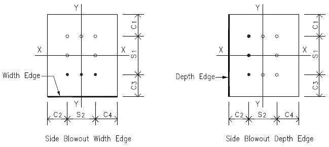
Side Edges Along X-X Axis - Width Edges
Anchor edge distance in Y direction
ca1
= min (c1 , c3 )
= 6.000
[in]
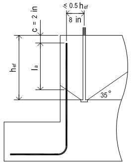
Anchor embedment depth
hef
= from user input
= 18.000
[in]
Side blowout check is required on this edge or not
= check if hef > 2.5 ca1
= True
ACI 318-19 17.6.4.1
Side blowout check is required
ACI 318-19 17.6.4.1
Anchor out-out distance edges along X direction
s2
= from user input
= 16.000
[in]
Anchor number along X direction
nw
= from user input
= 2
Anchor head net bearing area & conc strength
Abrg
= 2.24
[in2]
fc
= 4.5
[ksi]
Lightweight conc modification factor
λ
= 1.0
ACI 318-19 17.2.4.1
Single anchor side blowout capacity
Nsb
= 160 ca1 √Abrg λ √fc
= 96.32
[kips]
ACI 318-19 17.6.4.1
For multiple anchors along the edge, check if the anchor spacing is close enough so that side
blowout capacity shall be calculated as a group
ACI 318-19 17.6.4.2
Anchor spacing along X-X edges
sb
= s2 / (nw - 1)
= 16.000
[in]
Multiple tensile anchors space close and work as group or not
= check if sb < 6 ca1
= True
ACI 318-19 17.6.4.2
Multiple anchors group factor
= 1.44
ACI 318-19 17.6.4.2
Group anchor side blowout capacity
Nsbg
= 139.13
[kips]
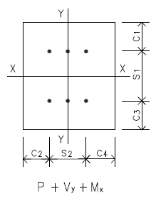
Max Single Anchor Tensile Force
Anchor group axial tensile force
P
= from user load input
= -116.00
[kips]
in tension
No of anchors in the group
nt
=
= 4
Single anchor tensile force
T
= P / nt
= 29.00
[kips]
No of anchors along side blowout edge
nbw
= from user input
= 2
Tensile force - anchors along potential blowout edge
Tw
= nbw x T
= 58.00
[kips]
Strength reduction factor
φtc
= 0.75
supplementary reinft present
ACI 318-19 17.5.3(b)
φtc Nsbg
= 0.75 x 139.13
= 104.35
[kips]
Seismic design strength reduction
= x 1.0 not applicable
= 104.35
[kips]
ACI 318-19 17.10.5.4(d)
ratio
= 0.56
> Tw
OK
When there are tensile anchors in the group which are not located on blowout edge, we need to use edge
anchors capacity above to work out anchor group tensile capacity
Group anchor no & no of anchor along blowout edge
nt
= 4
nbw
= 2
Group anchor tensile side blowout capacity
= 208.69
[kips]
Side Edges Along Y-Y Axis - Depth Edges
Anchor edge distance in X direction
ca2
= min (c2 , c4 )
= 6.000
[in]
Anchor embedment depth
hef
= from user input
= 18.000
[in]
Side blowout check is required on this edge or not
= check if hef > 2.5 ca2
= True
ACI 318-19 17.6.4.1
Side blowout check is required
ACI 318-19 17.6.4.1
Anchor out-out distance edges along X direction
s1
= from user input
= 16.000
[in]
Anchor number along X direction
nd
= from user input
= 2
Anchor head net bearing area & conc strength
Abrg
= 2.24
[in2]
fc
= 4.5
[ksi]
Lightweight conc modification factor
λ
= 1.0
ACI 318-19 17.2.4.1
Single anchor side blowout capacity
Nsb
= 160 ca2 √Abrg λ √fc
= 96.32
[kips]
ACI 318-19 17.6.4.1
For multiple anchors along the edge, check if the anchor spacing is close enough so that side
blowout capacity shall be calculated as a group
ACI 318-19 17.6.4.2
Anchor spacing along Y-Y edges
sb
= s1 / (nd - 1)
= 16.000
[in]
Multiple tensile anchors space close and work as group or not
= check if sb < 6 ca2
= True
ACI 318-19 17.6.4.2
Multiple anchors group factor
= 1.44
ACI 318-19 17.6.4.2
Group anchor side blowout capacity
Nsbg
= 139.13
[kips]
Max Single Anchor Tensile Force
Anchor group axial tensile force
P
= from user load input
= -116.00
[kips]
in tension
No of anchors in the group
nt
=
= 4
Single anchor tensile force
T
= P / nt
= 29.00
[kips]
No of anchors along side blowout edge
nbd
= from user input
= 2
Tensile force - anchors along potential blowout edge
Td
= nbd x T
= 58.00
[kips]
Strength reduction factor
φtc
= 0.75
supplementary reinft present
ACI 318-19 17.5.3(b)
φtc Nsbg
= 0.75 x 139.13
= 104.35
[kips]
Seismic design strength reduction
= x 1.0 not applicable
= 104.35
[kips]
ACI 318-19 17.10.5.4(d)
ratio
= 0.56
> Td
OK
When there are tensile anchors in the group which are not located on blowout edge, we need to use edge
anchors capacity above to work out anchor group tensile capacity
Group anchor no & no of anchor along blowout edge
nt
= 4
nbd
= 2
Group anchor tensile side blowout capacity
= 208.69
[kips]
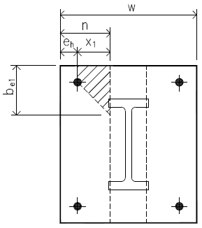
Corner Single Anchor Side Blowout
Check on corner single anchor side blowout capacity considering the corner effect factor
as per ACI 318-19 17.6.4.1.1
ACI 318-19 17.6.4.1.1
Anchor edge distance
ca1
= min (c1 , c3 )
= 6.000
[in]
ca2
= min (c2 , c4 )
= 6.000
[in]
Consider corner effect or not
= check if ca2 < 3 ca1
= True
ACI 318-19 17.6.4.1.1
Single anchor side blowout capacity
Nsb1
= (1 +
ca2/ca1
) /4 x N
sb = 48.16
[kips]
Max Single Anchor Tensile Force
Anchor group axial tensile force
P
= from user load input
= -116.00
[kips]
in tension
No of anchors in the group
nt
=
= 4
Single anchor tensile force
T
= P / nt
= 29.00
[kips]
Strength reduction factor
φtc
= 0.75
supplementary reinft present
ACI 318-19 17.5.3(b)
φtc Nsb
= 0.75 x 48.16
= 36.12
[kips]
Seismic design strength reduction
= x 1.0 not applicable
= 36.12
[kips]
ACI 318-19 17.10.5.4(d)
ratio
= 0.80
> T1
OK