Anchor Forces Calculation
Anchor Tensile Force Calculation
User Input
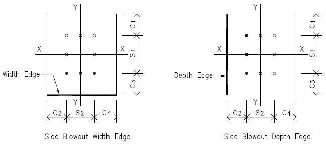
Anchor edge distance
c1u
= 13.000
[in]
c2u
= 10.000
[in]
c3u
= 13.000
[in]
c4u
= 10.000
[in]
Anchor out-out spacing
s1u
= 10.000
[in]
s2u
= 10.000
[in]
Anchor embedment depth
hef
= 20.000
[in]
Design Load - Load Case 1
Axial force
Axial P
= 545.00
[kips]
in compression
Shear forces
Vy
= 175.00
[kips]
Vx
= 0.00
[kips]
Moment forces
Mx
= 0.00
[kip-ft]
My
= 0.00
[kip-ft]
Design Load - Load Case 2
Axial force
Axial P
= -85.00
[kips]
in tension
Shear forces
Vy
= 175.00
[kips]
Vx
= 0.00
[kips]
Moment forces
Mx
= 0.00
[kip-ft]
My
= 0.00
[kip-ft]
Anchor Layout Plan

Load Case 1 - Anchor Additional Tension From Moment Caused by Vy
Shear key shear force
Vu
= from user load input
= 175.00
[kips]
Refer
to sketch below , shear key's shear reaction takes moment to base plate
center line and this moment will cause additional tensile force on
anchors
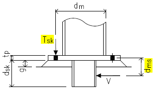
Base plate & grout thickness
tp
= 2.000
[in]
g
= 1.000
[in]
Shear key depth
dsk
= 8.000
[in]
Shear key shear V to base plate center moment arm distance
dms
= 0.5( dsk - g) + g + 0.5 tp
= 5.500
[in]
Moment by shear key shear
Mu
= Vu dms
= 80.21
[kip-ft]
Anchor out-out spacing - in shear direction
s1
= from user input
= 10.000
[in]
Column depth - in shear direction
d
= sect W18X86
= 18.400
[in]
Exterior anchhor moment arm
dm
= d + 0.5( s1 - d )
= 14.200
[in]
Anchor number along exterior anchhor
nbw
= from user input
= 2
Single anchor tension from moment caused by shear key
Tsk
=
Mudm x nbw
= 33.89
[kips]
Load Case 2 - Anchor Additional Tension From Moment Caused by Vy
Shear key shear force
Vu
= from user load input
= 175.00
[kips]
Refer
to sketch below , shear key's shear reaction takes moment to base plate
center line and this moment will cause additional tensile force on
anchors
Base plate & grout thickness
tp
= 2.000
[in]
g
= 1.000
[in]
Shear key depth
dsk
= 8.000
[in]
Shear key shear V to base plate center moment arm distance
dms
= 0.5( dsk - g) + g + 0.5 tp
= 5.500
[in]
Moment by shear key shear
Mu
= Vu dms
= 80.21
[kip-ft]
Anchor out-out spacing - in shear direction
s1
= from user input
= 10.000
[in]
Column depth - in shear direction
d
= sect W18X86
= 18.400
[in]
Exterior anchhor moment arm
dm
= d + 0.5( s1 - d )
= 14.200
[in]
Anchor number along exterior anchhor
nbw
= from user input
= 2
Single anchor tension from moment caused by shear key
Tsk
=
Mudm x nbw
= 33.89
[kips]