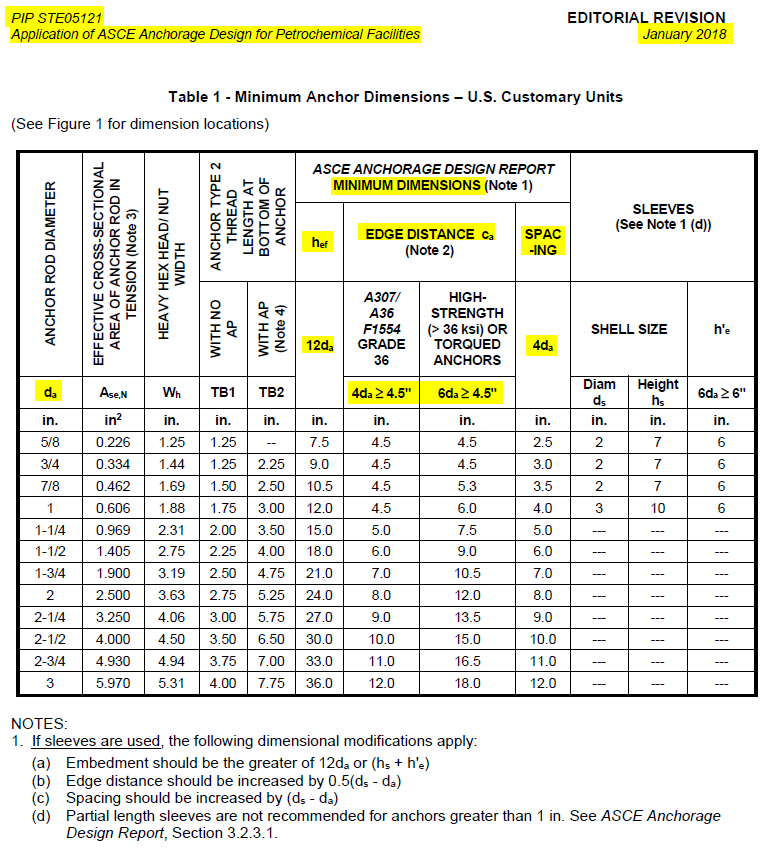
Anchor Forces Calculation
Anchor Tensile Force Calculation
User Input
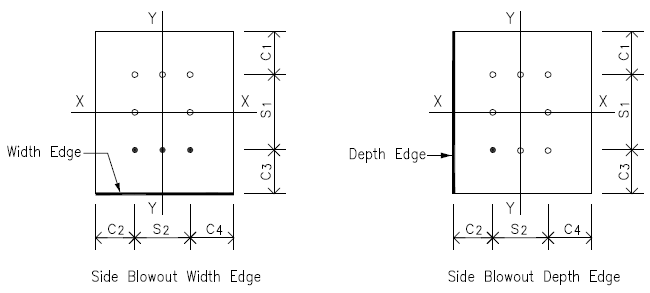
Anchor edge distance
c1u
= 9.500
[in]
c2u
= 9.500
[in]
c3u
= 9.500
[in]
c4u
= 9.500
[in]
Anchor out-out spacing
s1u
= 29.000
[in]
s2u
= 29.000
[in]
Anchor embedment depth
hef
= 60.000
[in]
Design Load - Load Case 1
Axial force
Axial P
= 3.90
[kips]
in compression
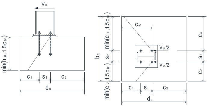
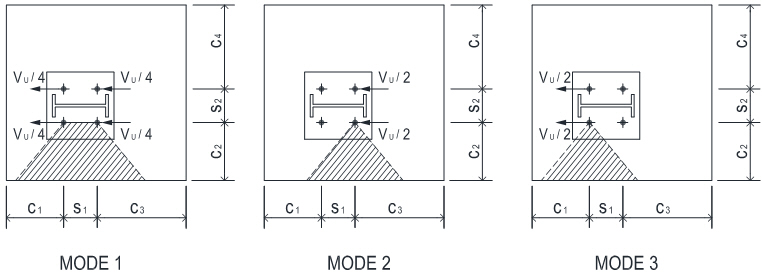
Shear forces
Vy
= 1.50
[kips]
Vx
= 0.00
[kips]
Moment forces
Mx
= 79.00
[kip-ft]
My
= 0.00
[kip-ft]
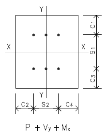
Anchor Layout Plan

Load Case 1 - Check on P + Vy + Mx
Anchor edge distance
c1
= 9.500
[in]
c2
= 9.500
[in]
c3
= 9.500
[in]
c4
= 9.500
[in]
Anchor out-out spacing
s1
= 29.000
[in]
s2
= 29.000
[in]
Anchor group load
Pu
= 3.90
[kips]
Vu
= 1.50
[kips]
Mu
= 79.00
[kip-ft]
Max Allowed Concrete Pressure
Bolt circle dia & edge distance
Dbc
= 29.000
[in]
e
= 3.000
[in]
Base plate area
A1
= 2
π4
( Dbc + 2 e ) = 962.11
[in2]
Bolt circle dia & edge distance
Dbc
= 29.000
[in]
c
= 9.500
[in]
Base plate area
A2
= 2
π4
( Dbc + 2 c ) = 1809.6
[in2]
ACI 318-19 Table 14.5.6.1
k
= min ( √A2 / A1 , 2 )
= 1.371
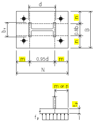
Column sect Custom Sect
d
= 18.000
[in]
bf
= 18.000
[in]
AISC Design Guide 1 - 3.1.2 on Page 15
Base plate cantilever dimension
m
= ( N - 0.8 d ) / 2
= 9.300
[in]
n
= ( B - 0.8 bf ) / 2
= 10.300
[in]
ACI 318-19
Concrete strength & strength reduction factor
fc
= 4.0
[ksi]
φc
= 0.65
Table 21.2.1 (d)
AISC Design Guide 1
Pedestal max bearing stress
fp(max)
= φc k 0.85 fc
= 3.031
[ksi]
3.1.1 on Page 14
Factored forces on base plate
Pu
= 3.90
[kips]
Mu
= 79.00
[kip-ft]
Eccentricity
e
= Mu / Pu
= 243.077
[in]
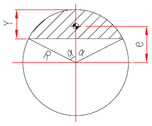
Calculate Circular Bolt Pattern Critical Eccentricity ecrit
Refer to sketch on the right, max allowed ecc when no tensile forces mobilized in anchors
is the ecc when
1) Max bearing stress fp(max) is reached so that Y reaches the min and e reaches the max
2) Axial compression Pu equals to bearing stress reaction resultant Pu = fp(max) A
as there is no anchor tension involved in the vertical forces equilibrium
is the ecc when
1) Max bearing stress fp(max) is reached so that Y reaches the min and e reaches the max
2) Axial compression Pu equals to bearing stress reaction resultant Pu = fp(max) A
as there is no anchor tension involved in the vertical forces equilibrium
Axial compression force & max allowed stress under base plate
Pu
= 3.90
[kips]
fp(max)
= 3.031
[ksi]
Base plate radius and stress block angle when Y is reached
R
= 17.500
[in]
α
= 10.170
Stress block area
A
=
R22
( 2α - sin(2α)) = 1.13
[in2]
Stress block length at angle of α
Y
= calc from angle α above
= 0.275
[in]
Max allowed ecc when no anchor is in tensin
e
=
4R sin3α3 (2α - sin(2α))
= 17.335
[in]
Critical eccentricity
ecrit
= e value calculated above
= 17.335
[in]
when e > ecrit , large moment case applied
Step 3 on Page 27
Anchor Tensile Force Calc - Group Anchor Subject to Moment
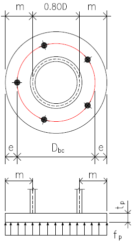
Design Basis and Assumptions
1. Assume base plate is rigid and anchor tensile forces are elastic linearly distributed as shown on the right.
2. The concrete bearing stress is assumed to be uniformly distributed as per AISC Design Guide 1 section 3.3.1
User can select the option of base plate thickness tp ≥ (max of base plate overhangs m or n) / 4 in
Anchor Bolt - Config & Setting to ensure that base plate has adequate rigidity to match above assumptions.
Anchor Bolt Dimensions
Circular anchor bolt circle dia & base plate dia
Dbc
= 29.000
[in]
Dbp
= 35.000
[in]
Column sect Custom Sect
OD
= 18.000
[in]
Loads on Anchor Group
Anchor group load
Pu
= 3.90
[kips] (C)
Mu
= 79.00
[kip-ft]
Along Anchor Bolt Line - Single Anchor Tensile Ti & No of Anchor Bolt ni
Anchor bolt line - moment arm
dm1
= 21.557
[in]
dm2
= 9.000
[in]
Bolt line 1 - single anchor T1
T1
= 12.20
[kips]
n1
= 2
Bolt line 2 - single anchor T2
T2
= 5.09
[kips]
n2
= 2
Sum of anchors tensile force
Tu
= n1 T1 + n2 T2
= 34.58
[kips]
No of anchors in anchor group resisting tension
nt
= n1 + n2
= 4
Resistance moment by anchor tensile
Mra
= n1 T1 dm1 + n2 T2 dm2
= 51.46
[kip-ft]
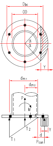
Moment by Concrete Pressure Reaction
Take the moment of concrtete pressure resultant Pcon to column flange/base plate intersect point A as
shown on above sketch on the right
shown on above sketch on the right
Pedestal max bearing stress
fp(max)
= φc k 0.85 fc
= 3.031
[ksi]
AISC DG1 3.1.1
Base plate radius and column dia
R
= 17.500
[in]
OD
= 18.000
[in]
Stress block length and angle at Y
Y
= 1.373
[in]
α
= 22.850
Conc stress block area
A
=
R22
( 2α - sin(2α)) = 12.54
[in2]
Conc stress block centroid to circular base plate center distance
e
=
4R sin3α3 (2α - sin(2α))
= 16.678
[in]
Conc stress resultant to point A moment arm
dc
= e - 0.5 OD
= 7.678
[in]
Concrete pressure stress resultant
Pcon
= fp(max) A
= 38.01
[kips]
Resistance moment by concrete stress resultant reaction
Mrc
= Pcon x dc
= 24.32
[kip-ft]
Below two sections are for verification purpose only. We want to verify that the anchor tensile forces and
concrete pressure block length Y shown above make the base plate achieving force equilibrium
concrete pressure block length Y shown above make the base plate achieving force equilibrium
Verify Vertical Force Equilibrium
Tensile anchors reaction on base plate - downward
Par
= n1 T1 + n2 T2
= 34.58
[kips]
Base plate compressive load- downward
Pu
= from user load input
= 3.90
[kips]
Sum of downward forces on base plate
Pdn
= Par + Pu
= 38.48
[kips]
Concrete pressure reaction on base plate - upward
Pcon
= qmax Y
= 38.01
[kips]
Sum of upward forces on base plate
Pup
= Pcon
= 38.01
[kips]
Conclusion : the vertical forces equilibrium is achieved
Summation of Moments Taken About Point A
Resistance moment by tensile anchors downward reaction forces
Mra
= n1 T1 dm1 + n2 T2 dm2
= 51.46
[kip-ft]
Resistance moment by concrete pressure reaction force
Mrc
= Pcon x dc
= 24.32
[kip-ft]
Sum of resistance moment
= Mra + Mrc
= 75.78
[kip-ft]
Load on base plate
Pu
= 3.90
[kips]
Mu
= 79.00
[kip-ft]
Column sect Custom Sect
d
= 18.000
[in]
Sum of moments from base plate loads taken to point A
= Mu - Pu x 0.5 OD
= 76.07
[kip-ft]
Conclusion : the summation of moments taken about point A equals to zero
Load Case 1 - P + Vy + Mx Reduced hef Calc
Anchor Embedment Depth hef Adjustment
Anchor embedment depth hef - If anchors are located less than 1.5hef from three or more edges,
hef needs to be shortened as per ACI 318-19 17.6.2.1.2
hef needs to be shortened as per ACI 318-19 17.6.2.1.2
ACI 318-19 17.6.2.1.2
Anchor
group edge distances are re-calculated base on tensile anchors in the
group as not all anchors mobilized tensile force under the moment
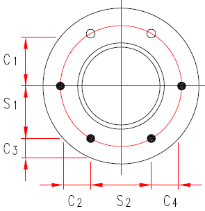
Anchor Group Dimensions
Anchor bolt circle dia & pedestal dia
Dbc
= 29.000
[in]
Dpd
= 48.000
[in]
Anchor spacing
s1
= 14.500
[in]
s2
= 14.500
[in]
Anchor edge distance
c1
= 19.125
[in]
c2
= 9.500
[in]
c3
= 10.321
[in]
c4
= 9.500
[in]
Max anchor spacing within the group used in effective anchor embedment depth calc
Max anchor spacing within the tensile anchors group
s1max
= 14.500
[in]
s2max
= 29.000
[in]
Anchor embedment depth - from user input
hef
= from user input
= 60.000
[in]
Anchors are located less than 1.5hef from three or more edges
= Yes
Max of edge distances not exceeding 1.5hef
ca,max
=
= 19.125
[in]
Max spacing between anchors within the group
s
=
= 29.000
[in]
Anchor embedment depth - adjusted
hef
= max (ca,max /1.5 , s /3)
= 12.750
[in]
ACI 318-19 17.6.2.1.2
Concrete Breakout - Tensile Anchors Eccentricity Factor - Ψec,N Calc
Modification factor for anchor groups loaded eccentrically in tension as per ACI 318-19 17.6.2.3.1
Along Anchor Bolt Line - Single Anchor Tensile Ti & No of Anchor Bolt ni
See calculation above for sketch showing the notations
of T1 ~ T2 and sb1 values shown below
of T1 ~ T2 and sb1 values shown below
Bolt line 1 - single anchor T1
T1
= 12.20
[kips]
n1
= 2
Bolt line 2 - single anchor T2
T2
= 5.09
[kips]
n2
= 2
Anchor distance to bolt line-1
de2
= 12.557
[in]
Eccentricity eN of Resultant Anchor Tensile Force
Take bolt line-1 as a rotating point, take moment to bolt line-1
Distance from anchors tensile resultant to bolt line-1
d1
=
n2 T2 de2n1 T1 + n2 T2
= 3.698
[in]
Distance from anchors group centroid to bolt line-1
d2
=
n2 de2n1 + n2
= 6.279
[in]
Ecc dist between anchor tensile resultant and anchor group CG
eN
= d2 - d1
= 2.580
[in]
Refer to calc above for details on reduced hef calc as per ACI 318-19 17.6.2.1.2
Anchor embedment depth
hef
= from calc above
= 12.750
[in]
ACI 318-19 Eq 17.6.2.3.1
Eccentricity modification factor
Ψec,N
=
1(1 + eN / 1.5hef )
≤ 1 = 0.881
ACI 318-19 Fig. R17.6.2.3.1
Definition of eN for an anchor group
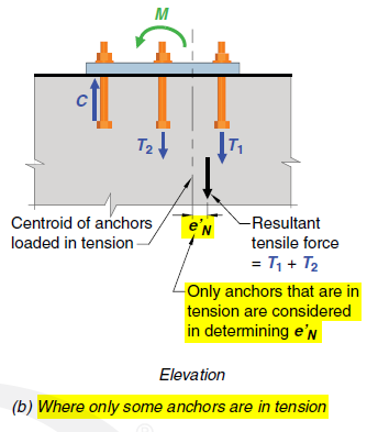
Definition of eN for an anchor group