Result Summary - Overall
Anchorage Design
Code=ACI 318-19

Result Summary - Overall
geometries & weld limitations = PASS
limit states max ratio 
0.50
PASS
 
Vertical Vessel Leg Anchor
geometries & weld limitations = PASS
limit states max ratio 
0.50
PASS


  Sketch
Anchorage Design
Code=ACI 318-19


Vertical Vessel Anchor Forces Calculation
 
Design Basis and Assumptions
The design of circular pattern anchor bolt group uses the Method 2 Sawcut with hef' and Neutral Axis at Center as stated in the
following references
 
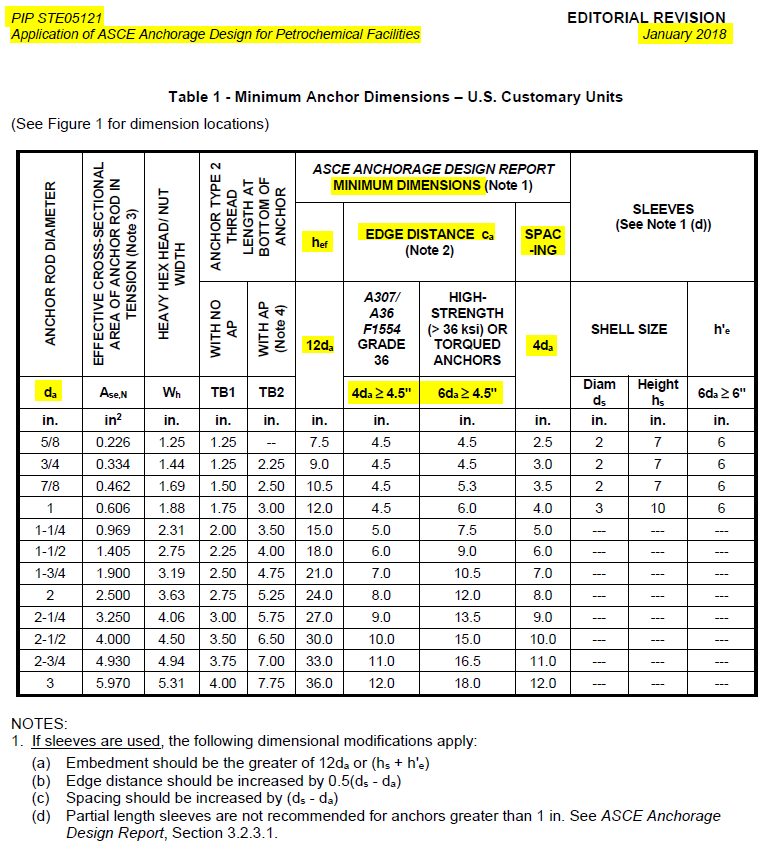
1. ASCE Anchorage Design for Petrochemical Facilities - 2013 Example 2 Step 5(c) on Page 145
2. ASCE 2010 Structural Congress - Concrete Breakout Strength in Tension for Vertical Vessel Anchorage in Octagon Pedestals
 
The 
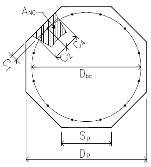
design of circular pattern anchor bolt group is simplified as design of a single anchor bolt with 3 side free edges sawcut at midway between adjacent anchors. The simplified design method uses the following assumptions
 
1. The moment is resisted only by the anchor bolt group and it does not take into account the contribution of concrete compression force
    against base plate in the moment equilibrium
2. The neutral axis is not shifted and is located at center of vessel
3. It does not consider strain compatibility between the concrete and steel elements which comprise the anchorage.
4. In the assumed 3 side free edges sawcut model, when anchor is located less than 1.5hef from three or more edges, the reduced hef' is
    used to calculate concrete projected failure area ANC
 
The utilization ratio of simplified method used in this calculation is conservative compared to the accurate but more complex approach.
The detail comparison and analysis of this simplified method is addressed in reference 2 above.
 
Octagon Concrete Mat Geometrics
 
Octagon mat face-to-face distance
Dp
 = from user input
 = 196.85
[in]
Anchor bolt bolt circle diameter
Dbc
 = from user input
 = 157.50
[in]
No of anchor bolt
Na
 = from user input
 = 20
 
Anchor bolt edge distance
c1
 = ( Dp - Dbc ) / 2
 = 19.68
[in]
c3
 = Dp - c1
 = 177.18
[in]
c2
 = 
Dbc/2
tan
360/ 2 Na
 = 12.47
[in]
c4
 = c2
 = 12.47
[in]
 
 
ACI 318-19 17.6.2.1.2
Effective embedment depth
hef'
 = 
 = 13.12
[in]
Octagon side edge length
Sp
 = 
Dp/( 1 + 2)
 = 81.54
[in]


Octagon shape conc mat area
Ap
 = 
 = 32101.5
[in2]

Projected conc failure area
ANC
 = 
Ap - (π/4) [Dbc - min(3hef' , Dbc )]2/Na
 = 1056.9
[in2]

 
Single Anchor Bolt Tensile and Shear Load
PIP STE03350 -2008
Factored compression at top of concrete pedestal
Pu
 = 
Mu/0.667 Dbc
+ 0.9
De/2
 = 135.54
[kips]
Section 4.6.1 Eq 5
 
Factored shear at base of vessel
Vu
 = from user input
 = 29.90
[kips]

 
Vessel base to concrete support surface friction factor
μ
 = from user input
 = 0.55
Section 4.6.2
Strength reduction factor
φ
 = 
 = 0.75
Section 4.6.2
Factored frictional resistance
φ Vf
 = φ μ Pu
 = 55.91
[kips]
Section 4.6.1 Eq 6
 
> Vu  shear load taken by the friction
Section 4.6.2 Eq 7
 
Factored single anchor shear load
Vua
 = shear load taken by the friction
 = 0.00
[kips]


Anchor Tensile - Uplift LCB by Wind
Factored base moment - wind
Muw
 = from user input
 = 1000.9
[kip-ft]

Vessel empty weight
De
 = from user input
 = 47.00
[kips]

 
Factored single anchor tensile load
Nuaw
 = 
4 Muw/Na Dbc
- 0.9
De/Na
 = 13.14
[kips]
Section 4.6.1 Eq 4


Anchor Tensile - Uplift LCB by Seismic
Factored base moment - seismic
Mus
 = from user input
 = 434.20
[kip-ft]

Vessel operating weight
Do
 = from user input
 = 280.80
[kips]

 
When
4 Mus/Na Dbc
< 0.9
Do/Na
, there is no tensile load mobilized on anchor
Factored single anchor tensile load
Nuas
 = 
4 Mus/Na Dbc
- 0.9
Do/Na
 = 0.00
[kips]
Section 4.6.1 Eq 4


Factored single anchor tensile load - max
Nua
 = max ( Nuaw , Nuas )
 = 13.14
[kips]


  Vertical Vessel Anchor Bolt
    Pt =13.1 kip     V =0.0 kip
Code=ACI 318-19

Result Summary
geometries & weld limitations = PASS
limit states max ratio 
0.50
PASS
 
 
Min Anchor Dimensions Check Per PIP STE05121 - Optional
PASS
 
Min Anchor Dimensions Check
 
Check min anchor dimensions as per PIP STE05121 Application of ASCE Anchorage Design for Petrochemical Facilities - 2018   Table 1 as shown below.
 
This check is NOT a code requirement.   User can turn this check On/Off by changing setting at Anchor Bolt --> Anchor Bolt - Config & Setting --> Check min anchor spacing and edge distance as per PIP STE05121 Table 1
 
Anchor Rod Inputs


Anchor rod grade and dia
grade
 = F1554 Gr36
da
 = 1.000
[in]

 
Anchor sleeve dia and height
ds
 = 3.000
[in]
hs
 = 10.000
[in]

 
Min Anchor Edge Distance


Anchor edge distance
c1
 = 19.675
[in]
c2
 = 12.473
[in]

c3
 = 177.175
[in]
c4
 = 12.473
[in]

 
Min anchor edge distance required
cmin
 = from PIP STE05121 Table 1 below
 = 5.500
[in]
PIP STE05121 Table 1
 
Min anchor edge distance
c
 = min(c1 , c2 , c3 , c4 )
 = 19.675
[in]

 ≥ cmin
OK
Min Anchor Embedment Depth


Min anchor embedment required
hmin
 = from PIP STE05121 Table 1 below
 = 16.000
[in]
PIP STE05121 Table 1
 
Min anchor embedment depth
hef
 = from user input
 = 18.000
[in]

 ≥ hmin
OK


Table 1 from PIP STE05121 Application of ASCE Anchorage Design for Petrochemical Facilities - 2018


Anchor Rod Tensile Resistance
ratio = 13.1 / 26.4
0.50
PASS
 
Anchor rod effective section area
Ase
 = 0.61
[in2]
futa
 = 58.0
[ksi]

Anchor rod steel strength in tension
Nsa
 = Ase futa
 = 35.15
[kips]
ACI 318-19 17.6.1.2


Max Single Anchor Tensile Force
 
Anchor group axial tensile force
P
 = from user load input
 = -13.14
[kips]
in tension
No of anchors in the group
nt
 = 
 = 1

 
Single anchor tensile force
T
 = P / nt
 = 13.14
[kips]


Strength reduction factor
φts
 = 0.75
ACI 318-19 17.5.3(a)
φts Nsa
 = 0.75 x 35.15
 = 26.36
[kips]

ratio
 = 0.50
 > T
OK
 
Anchor Concrete Tensile Breakout Resistance
ratio = 13.1 / 35.1
0.37
PASS
 
Anchor embedment depth-adjusted
hef
 = from Anchor Forces Calculation above
 = 13.117
[in]

Conc strength & lightweight conc factor
fc
 = 4.4
[ksi]
λ
 = 1.0
ACI 318-19 17.2.4.1
 
Single anchor concrete breakout strength
Nb
 = 24λ fc h1.5ef If hef < 11" or hef > 25"
 = 76.98
[kips]
ACI 318-19 17.6.2.2.1
16λ fc h5/3ef   If 11" ≤ hef  ≤ 25"
ACI 318-19 17.6.2.2.3


Refer to Vertical Vessel Anchor Forces Calculation above for vertical vessel c1 ~ c4
calculation and design assumptions
 
Anchor edge distance
c1
 = 19.675
[in]
c2
 = 12.473
[in]

c3
 = 177.175
[in]
c4
 = 12.473
[in]

 
Anchor out-out spacing
s1
 = 0.000
[in]
s2
 = 0.000
[in]


Refer to Vertical Vessel Anchor Forces Calculation above for the details of vertical vessel circular anchor group
and single anchor of that group projected failure area ANC1 calculation as shown below
 
ANC1
 = 
 = 1056.9
[in2]

 
ANco
 = 9 h2ef
 = 1548.4
[in2]
ACI 318-19 17.6.2.1.4
 
No of anchors in the group resisting tension
nt
 = from Anchor Forces Calculation above
 = 1

ANc
 = min( ANc1 , nt ANco )
 = 1056.9
[in2]
ACI 318-19 17.6.2.1.1


Eccentricity modification factor
Ψec,N
 = from Anchor Forces Calculation above
 = 1.000
ACI 318-19 17.6.2.3.1
 
Min edge distance
cmin
 = min(c1 , c2 ,c3 ,c4 )
 = 12.473
[in]

Edge modification factor
Ψed,N
 = min[0.7 +
0.3cmin/1.5hef
, 1.0]
 = 0.890
ACI 318-19 17.6.2.4.1
Conc cracking modification factor
Ψc,N
 = 
 = 1.00
ACI 318-19 17.6.2.5.1
Conc splitting modification factor
Ψcp,N
 = 
 = 1.00
ACI 318-19 17.6.2.6.1
Concrete breakout resistance
Ncbg
 = 
ANc/ANco
Ψec,N Ψed,N Ψc,N Ψcp,N Nb
 = 46.78
[kips]
ACI 318-19 17.6.2.1b
 
Sum of anchors tensile force in anchor group
Nu
 = from Anchor Forces Calculation above
 = 13.14
[kips]

 
Strength reduction factor
φtc
 = 0.75
  supplementary reinft present
ACI 318-19 17.5.3(b)
φtc Ncbg
 = 0.75 x 46.78
 = 35.08
[kips]

 
Seismic design strength reduction
 = x 1.0   not applicable
 = 35.08
[kips]
ACI 318-19 17.10.5.4(b)
 
ratio
 = 0.37
 > Nu
OK
 
Anchor Pullout Resistance
ratio = 13.1 / 36.6
0.36
PASS
 
Anchor head net bearing area & conc strength
Abrg
 = 1.50
[in2]
fc
 = 4.4
[ksi]

Single bolt pullout resistance
Np
 = 8 Abrg fc
 = 52.23
[kips]
ACI 318-19 17.6.3.2.2a
Pullout cracking factor
ΨcP
 = for cracked concrete
 = 1.00
ACI 318-19 17.6.3.3.1(b)


Max Single Anchor Tensile Force
 
Anchor group axial tensile force
P
 = from user load input
 = -13.14
[kips]
in tension
No of anchors in the group
nt
 = 
 = 1

 
Single anchor tensile force
T
 = P / nt
 = 13.14
[kips]


Strength reduction factor
φtc
 = 0.70
 pullout strength is always Condition B
ACI 318-19 17.5.3(c)
φtc Npn
 = φtc ΨcP Np
 = 36.56
[kips]

 
Seismic design strength reduction
 = x 1.0   not applicable
 = 36.56
[kips]
ACI 318-19 17.10.5.4(c)
 
ratio
 = 0.36
 > T
OK
 
Anchor Side Blowout Resistance
N/A
Anchor Inputs


Anchor edge distance
c1
 = 19.675
[in]
c2
 = 12.473
[in]

c3
 = 177.175
[in]
c4
 = 12.473
[in]

 
Anchor out-out spacing
s1
 = 0.000
[in]
s2
 = 0.000
[in]


Anchor edge distance - min
ca1
 = min (c1 , c2 , c1 , c4 )
 = 12.473
[in]

Anchor embedment depth
hef
 = from user input
 = 18.000
[in]

 
Side blowout check is required on this edge or not
 = check if hef > 2.5 ca1
 = False
ACI 318-19 17.6.4.1
 
Side blowout check is NOT required
ACI 318-19 17.6.4.1


Anchor Group Governing Tensile Resistance
 
Anchor group governing tensile resistance is the minimum value of the resistance values in
the following limit states
 
No of anchors in anchor group
resisting tension
nt
 = from Anchor Forces Calculation above
 = 1

 
Anchor rod tensile resistance
nt φ Nsa
 = 1 x 26.36
 = 26.36
[kips]

 
Anchor concrete breakout resistance
φ Ncbg
 = from anchor conc breakout calc above
 = 35.08
[kips]

 
Anchor pullout resistance
nt φ Npm
 = 1 x 36.56
 = 36.56
[kips]

 
Anchor side blowout resistance
φ Nsbg
 = from anchor side blowout calc above
 = N/A

 
Anchor group governing tensile resistance
φ Nn
 = minimum of above values
 = 26.36
[kips]


Anchor Shear Resistance and Tension - Shear Interaction
N/A
 
There is no shear load from user load input or shear key is used and all shear is taken by shear key, so
Anchor Shear Resistance and Tension - Shear Interaction checks are Not Applicable


Anchor Seismic Design
N/A
 
Seismic - Tension
    Not Applicable
ACI 318-19 17.10.5.1
 
Seismic SDC < C or E <= 0.2U , additional seismic requirements in ACI 318-19 17.10.5.3 is NOT required
ACI 318-19 17.10.5.3
 
 
Seismic - Shear
    Not Applicable
ACI 318-19 17.10.6.1
 
There is no shear load applied to anchor/anchor group, so Seismic Shear check is NOT required