|
|
|
|
|
|
|
|
|
|
|
|
|
CRANE RUNWAY BEAM DESIGN - CSA S16-14
|
|
|
|
|
|
|
|
Crane runway design based on
|
|
|
|
|
|
Code Abbreviation
|
|
CSA S16-14 Design of Steel Structures
|
CSA S16-14
|
|
AISC Design Guide 7: Industrial Buildings-Roofs to Anchor Rods 2nd Edition
|
AISC Design Guide 7
|
|
|
|
Crane runway beam section
|
Label
|
|
|
|
Section Properties
|
|
|
|
|
|
|
|
|
|
|
Label
|
|
|
|
|
|
|
|
|
|
|
|
A
|
=
|
Label
|
[mm2]
|
dall
|
=
|
Label
|
[mm]
|
|
|
|
top yT
|
=
|
Label
|
[mm]
|
bott. yB
|
=
|
Label
|
[mm]
|
|
|
|
Ix
|
=
|
Label
|
[mm4]
|
Iy
|
=
|
Label
|
[mm4]
|
|
|
|
top SxT
|
=
|
Label
|
[mm3]
|
bott. SxB
|
=
|
Label
|
[mm3]
|
|
|
|
Sy
|
=
|
Label
|
[mm3]
|
|
|
|
|
|
|
|
Zx
|
=
|
Label
|
[mm3]
|
Zy
|
=
|
Label
|
[mm3]
|
|
|
|
rx
|
=
|
Label
|
[mm]
|
ry
|
=
|
Label
|
[mm]
|
|
|
|
J
|
=
|
Label
|
[mm4]
|
Cw
|
=
|
Label
|
[mm6]
|
|
|
Top Flange
|
|
|
|
|
|
|
|
|
|
|
|
Af
|
=
|
Label
|
[mm2]
|
dall / Af
|
=
|
Label
|
[mm-1]
|
|
|
|
rT
|
=
|
Label
|
[mm]
|
ryt
|
=
|
Label
|
[mm]
|
|
|
|
It
|
=
|
Label
|
[mm4]
|
|
|
|
|
|
|
|
St
|
=
|
Label
|
[mm3]
|
Zt
|
=
|
Label
|
[mm3]
|
|
|
W Section
|
|
|
|
|
|
|
|
|
|
|
|
A
|
=
|
Label
|
[mm2]
|
|
|
|
|
|
|
|
d
|
=
|
Label
|
[mm]
|
bf
|
=
|
Label
|
[mm]
|
|
|
|
tw
|
=
|
Label
|
[mm]
|
tf
|
=
|
Label
|
[mm]
|
|
|
|
h
|
=
|
Label
|
[mm]
|
|
|
|
|
|
|
|
k
|
=
|
Label
|
[mm]
|
k1
|
=
|
Label
|
[mm]
|
|
|
|
J
|
=
|
Label
|
[mm4]
|
Cw
|
=
|
Label
|
[mm6]
|
|
|
Channel Section
|
|
|
|
|
|
|
|
|
|
|
|
A
|
=
|
Label
|
[mm2]
|
|
|
|
|
|
|
|
d
|
=
|
Label
|
[mm]
|
bf
|
=
|
Label
|
[mm]
|
|
|
|
tw
|
=
|
Label
|
[mm]
|
tf
|
=
|
Label
|
[mm]
|
|
|
|
h
|
=
|
Label
|
[mm]
|
k
|
=
|
Label
|
[mm]
|
|
|
|
J
|
=
|
Label
|
[mm4]
|
Cw
|
=
|
Label
|
[mm6]
|
|
|
|
|
|
|
|
|
|
|
|
|
|
W section yield strength
|
Fwy
|
=
|
Label
|
[MPa]
|
|
|
|
|
|
|
Cap channel or plate yield strength
|
Fcy
|
=
|
Label
|
[MPa]
|
|
|
|
|
|
|
Runway beam unbraced length
|
Lb
|
=
|
Label
|
[mm]
|
|
|
|
|
|
|
|
|
Design Forces
|
|
|
|
|
|
|
|
|
|
|
Bending moment x-x axis
|
|
|
|
|
Mx
|
=
|
Label
|
[kN-m]
|
|
|
Bending moment y-y axis - top flange
|
|
My-t
|
=
|
Label
|
[kN-m]
|
|
|
Bending moment y-y axis - bottom flange
|
|
My-b
|
=
|
Label
|
[kN-m]
|
|
|
Shear along y-y axis
|
|
|
|
|
Vy
|
=
|
Label
|
[kN]
|
|
|
|
Conclusion
|
|
|
|
|
|
|
|
|
CSA S16-14
|
|
Overall
|
|
|
|
|
ratio
|
=
|
Label
|
Label
|
|
|
|
|
Local buckling
|
|
|
|
|
|
|
|
Label
|
|
|
Find Lyr by setting Mu=Myr
|
Label
|
|
|
Label
|
13.6 e) i)
|
|
Bending about the X-X axis
|
|
|
|
|
ratio
|
=
|
Label
|
Label
|
|
|
Bending about the Y-Y axis in the top flange
|
ratio
|
=
|
Label
|
Label
|
|
|
Bending about the Y-Y axis in bottom flange -underhung crane
|
ratio
|
=
|
Label
|
Label
|
|
|
Label
|
|
|
|
ratio
|
=
|
Label
|
Label
|
|
|
Shear along Y-Y axis
|
|
|
|
|
ratio
|
=
|
Label
|
Label
|
|
|
Web sdesway buckling
|
|
|
|
|
ratio
|
=
|
Label
|
Label
|
|
|
|
|
Runway beam vertical deflection
|
|
|
|
|
ratio
|
=
|
Label
|
Label
|
|
|
Runway beam lateral deflection
|
|
|
|
|
ratio
|
=
|
Label
|
Label
|
|
|
|
|
Underhung crane bottom flange local bending
|
ratio
|
=
|
Label
|
Label
|
View Detail Calc
|
|
|
Design Basis & Assumption
|
|
|
|
|
|
|
|
|
Code Reference
|
|
1. The crane runway beam is designed as simple span beam.
|
AISC Design Guide 7
|
2. If A36 channel cap is used on A992 W section then lateral
torsional buckling and weak axis flexure
strength must be calculated based on A36 yield stress.
|
Section 18.1.4 on Page 57
|
3. For bending moment about the X axis, the moment caused
by runway beam and rail self weight is
calculated at beam midspan as maximum and added to the maximum
moment caused by crane
moving load. Even though the maximum moment caused by crane moving
load may not be at the
beam midspan, this conservative approach rarely makes a significant
change in the final combined
Mx value used in the runway beam design.
|
|
|
|
CALCULATION
|
|
|
|
|
|
|
|
|
|
|
|
|
Check Local Buckling
|
|
|
|
|
|
|
|
|
|
|
|
|
W Shape Classification
|
|
|
|
|
|
|
|
|
|
|
Flange of W shape
|
|
|
|
|
|
|
|
|
CSA S16-14
|
|
Class 2 limit
|
lp
|
=
|
170 / sqrt (Fwy)
|
=
|
Label
|
|
Table 2
|
|
Class 3 limit
|
lr
|
=
|
200 / sqrt (Fwy)
|
=
|
Label
|
|
|
|
|
bf / 2tf
|
=
|
Label
|
|
|
|
Label
|
|
|
Web of W shape
|
|
|
|
|
|
|
|
|
|
|
Class 2 limit
|
lp
|
=
|
1700 / sqrt (Fwy)
|
=
|
Label
|
|
Table 2
|
|
Class 3 limit
|
lr
|
=
|
1900 / sqrt (Fwy)
|
=
|
Label
|
|
|
|
|
h / tw
|
=
|
Label
|
|
|
|
Label
|
|
|
W shape classification
|
|
|
|
|
|
|
Label
|
|
|
|
|
Channel Classification
|
|
|
|
|
|
|
|
|
|
|
Flange of Channel
|
|
|
|
|
|
|
|
|
CSA S16-14
|
|
Class 2 limit
|
lp
|
=
|
170 / sqrt (Fwy)
|
=
|
Label
|
|
Table 2
|
|
Class 3 limit
|
lr
|
=
|
200 / sqrt (Fwy)
|
=
|
Label
|
|
|
|
|
bf / tf
|
=
|
Label
|
|
|
|
Label
|
|
|
Web of Channel (flange cover plate between lines of welds)
|
|
|
|
|
|
Class 2 limit
|
lp
|
=
|
525 / sqrt (Fcy)
|
=
|
Label
|
|
Table 2
|
|
Class 3 limit
|
lr
|
=
|
670 / sqrt (Fcy)
|
=
|
Label
|
|
|
|
bf (W shape) / tw (C channel)
|
=
|
Label
|
|
|
|
|
|
|
|
|
|
|
|
|
|
Label
|
|
|
Channel shape classification
|
|
|
|
|
|
|
Label
|
|
|
Cap Plate Classification
|
|
|
|
|
CSA S16-14
|
|
Flange Cover Plate Between Lines of Welds
|
|
|
|
|
|
|
Class 2 limit
|
lp
|
=
|
525 / sqrt (Fpy)
|
=
|
Label
|
|
Table 2
|
|
Class 3 limit
|
lr
|
=
|
670 / sqrt (Fpy)
|
=
|
Label
|
|
|
|
Cap plate classification
|
bf / tp
|
=
|
Label
|
|
|
|
Label
|
|
|
|
|
|
|
|
|
|
|
|
|
|
Label
|
|
|
Label
|
|
|
|
Label
|
|
|
|
|
|
|
|
|
|
|
|
|
|
Calculate Equivalent Top Flange
|
|
|
|
|
|
|
|
|
|
|
Top flange
|
Af
|
=
|
Label
|
[mm2]
|
It
|
=
|
Label
|
[mm4]
|
|
|
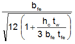
Equivalent top flange
|
bfe
|
=
|

|
=
|
Label
|
[mm]
|
|
|
|
tfe
|
=
|
Af / bfe
|
=
|
Label
|
[mm]
|
|
|
|
|
|
|
|
|
|
|
|
|
|
Monosymmetric Wide Flange Torsional Section Properties
|
CSA S16-14
|
|
|
|
Refer to CISC Torsional Section Properties Of Steel Shapes-2002 Page 10 for
the definitions and formulas used to calculate the following torsional section properties
|
|
|
|
|
St Venant and Warping constant
|
J
|
=
|
Label
|
[mm4]
|
Cw
|
=
|
Label
|
[mm6]
|
|
|
|
d-t
|
=
|
dall - ( tfe + tf ) /2
|
=
|
Label
|
[mm]
|
|
|
|
|
Asymmetry parameter
|
bx
|
=
|
|
=
|
Label
|
[mm]
|
13.6 e) ii)
|
|
|
|
Shear center location
|
a
|
=
|

|
=
|
Label
|
|
|
|
|
yo
|
=
|
yT - 0.5tfe - a (d-t)
|
=
|
Label
|
[mm]
|
|
|
Refer to CISC Torsional Section Properties Of Steel Shapes-2002 Page 12 for
the definitions and formulas used to calculate the following torsional section properties
|
|
|
|
|
St Venant and Warping constant
|
J
|
=
|
Label
|
[mm4]
|
Cw
|
=
|
Label
|
[mm6]
|
|
|
|
r
|
=
|
It / Iy
|
=
|
Label
|
|
|
|
|
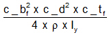
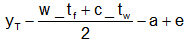
e
|
=
|
|
=
|
Label
|
[mm]
|
|
|
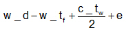
Top & bott flange shear center dist
|
h
|
=
|
|
=
|
Label
|
[mm]
|
|
|
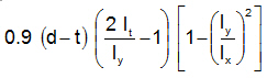
Asymmetry parameter
|
bx
|
=
|
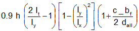
|
=
|
Label
|
[mm]
|
13.6 e) ii)
|
|
|
|
|
a
|
=
|
(1 - r ) x h
|
=
|
Label
|
[mm]
|
|
|
Shear center location
|
yo
|
=
|
|
=
|
Label
|
[mm]
|
|
|
Check Bending about X-X Axis
|
|
|
|
|
|
CSA S16-14
|
|
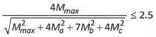
Moment gradient
|
|
|
|
|
|
|
|
|
|
|
|
Mmax
|
=
|
Label
|
[kNm]
|
M at L/4 Ma
|
=
|
Label
|
[kNm]
|
|
|
M at 2L/4 Mb
|
=
|
Label
|
[kNm]
|
M at 3L/4 Mc
|
=
|
Label
|
[kNm]
|
|
|
|
|
|
w3
|
=
|
|
=
|
Label
|
|
13.6 e) ii)
|
|
For underhung crane, increase w3 by multiplying
1.4
|
w3
|
=
|
min( w3 x 1.4 , 3)
|
=
|
Label
|
|
|
|
|
|
Critical elastic moment
|
Mu
|
=
|
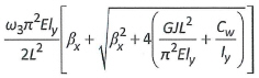
|
=
|
Label
|
[kNm]
|
13.6 e) ii)
|
|
|
|
|
Myr
|
=
|
0.7 SxB Fy
|
=
|
Label
|
[kNm]
|
13.6 e) i)
|
|
|
Mp
|
=
|
Zx Fwy
|
=
|
Label
|
[kNm]
|
|
|
When Mu > Myr
|
|
|
|
|
|
|
|
|
13.6 e) i)
|
|
|
Mrx
|
=
|
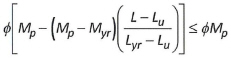
|
=
|
Label
|
[kNm]
|
|
|
|
|
where
|
Lu
|
=
|
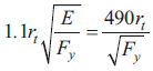
|
=
|
Label
|
[mm]
|
|
|
|
|
|
rt
|
=
|
|
=
|
Label
|
[mm]
|
|
|
|
|
depth of web in compression
|
hc
|
=
|
yT -tfe
|
=
|
Label
|
[mm]
|
|
|
|
Lyr
|
=
|
length L obtained by setting Mu=Myr
|
=
|
Label
|
[mm]
|
|
|
|
|
|
Label
|
Label
|
|
|
When Mu <= Myr
|
|
|
|
|
|
|
|
|
13.6 e) ii)
|
|
|
Mrx
|
=
|
f Mu
|
=
|
Label
|
[kNm]
|
|
|
|
ratio
|
=
|
Mx / Mrx
|
|
=
|
Label
|
Label
|
|
|
|
|
Check Bending about Y-Y Axis
|
|
|
|
|
|
|
|
|
|
Top Flange - Bending about Y-Y Axis
|
|
|
|
|
|
|
Check top flange class, for W check W flange only, for W+Cap Channel check both
W and channel flange
|
|
|
|
|
Top flange class
|
|
=
|
Label
|
|
|
|
|
|
For class 2 top flange
|
Mry-t
|
=
|
f Fy Zt
|
|
=
|
Label
|
[kN-m]
|
|
|
For class 3 top flange
|
Mry-t
|
=
|
f Fy St
|
|
=
|
Label
|
[kN-m]
|
|
|
|
ratio
|
=
|
My-t / Mry-t
|
|
=
|
Label
|
Label
|
|
|
|
|
Bottom Flange - Bending about Y-Y Axis
|
|
|
|
|
|
|
Bottom flange class
|
|
=
|
Label
|
|
|
|
|
|
For class 2 top flange
|
Mry-b
|
=
|
f Fy Zb
|
|
=
|
Label
|
[kN-m]
|
|
|
For class 3 top flange
|
Mry-b
|
=
|
f Fy Sb
|
|
=
|
Label
|
[kN-m]
|
|
|
|
ratio
|
=
|
My-b / Mry-b
|
|
=
|
Label
|
Label
|
|
|
|
|
|
|
|
|
|
|
|
|
Check Biaxial Bending on Top Flange
|
|
|
|
|
CSA S16-14
|
|
Biaxial bending - compression in top flange
|
|
Mx / Mrx + My-t / Mry-t
|
=
|
Label
|
Label
|
13.6 f)
|
|
Check Biaxial Bending on Bottom Flange
|
|
|
|
|
CSA S16-14
|
|
Biaxial bending -
tension in bottom flange
|
|
Mx /
( f SxBFy
)
+ My-b / Mry-b
|
=
|
Label
|
Label
|
13.6 f)
|
|
|
|
|
|
|
|
|
|
|
|
Check Shear along Y-Y Axis
|
|
|
|
|
|
CSA S16-14
|
|
|
h / tw
|
=
|
Label
|
|
|
|
|
|
|
|
|
|
Fs
|
=
|
0.66 Fy
|
|
=
|
Label
|
[MPa]
|
13.4.1.1 a) i)
|
|
Fs
|
=
|

|
=
|
Label
|
[MPa]
|
13.4.1.1 a) ii)
|
|
Fs
|
=
|

|
=
|
Label
|
[MPa]
|
13.4.1.1 a) iii)
|
|
|
|
|
Vr
|
=
|
f (d tw) Fs
|
=
|
Label
|
[kN]
|
13.4.1.1
|
|
|
ratio
|
=
|
Vy / Vr
|
|
|
=
|
Label
|
Label
|
|
|
|
|
|
|
|
|
|
|
|
|
|
Check Web Sidesway Buckling
|
|
|
|
|
|
AISC 360-10
|
|
|
|
There is no web sidesway buckling provision in CSA S16-14 code. AISC 360-10 section
J10.4 is
used to check the web sidesway buckling.
Web sidesway buckling check is necessary when the crane runway beam has long span
between
supporting columns and its bottom tension flange is not braced along the long span.
|
|
|
|
|
(h / tw) / (Lb / bf)
|
=
|
Label
|
Label
|
|
|
|
J10.4 (b)
|
|
|
Mu
|
=
|
Mx
|
=
|
Label
|
[kN-m]
|
|
|
|
My
|
=
|
min( SxT , SxB ) Fwy
|
=
|
Label
|
[kN-m]
|
|
|
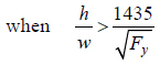
When Mu < My
|
Cr
|
=
|
Label
|
[MPa]
|
|
|
|
|
|
|
When Mu >= My
|
Cr
|
=
|
Label
|
[MPa]
|
|
|
|
|
|
|
|
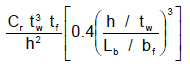
Rn
|
=
|
|
=
|
Label
|
[kN]
|
Eq J10-7
|
|
|
f
|
=
|
|
=
|
Label
|
|
|
|
|
Pv-impt
|
=
|
(1.25xPbr+1.5xPlt) x a
impact factor
|
=
|
Label
|
[kN]
|
|
|
|
ratio
|
=
|
Pv-impt / f Rn
|
=
|
Label
|
Label
|
|
|
|
The limit state of web sidesway buckling does not apply
|
Label
|
J10.4 (b) (ii)
|
|
|
|
|
|
|
|
|
|
|
|
|
Check Runway Beam Deflection
|
|
|
|
|
|
Code Reference
|
|
|
|
Crane serviceability criteria based on
|
|
|
CISC Guide for the Design of Crane-Supporting Steel Structures 2nd Edition
|
Table 4.1 item 14,15
|
|
AISC Design Guide 7: Industrial Buildings-Roofs to Anchor Rods 2nd Edition
|
Section 18 on Page 56
|
CMAA 70-04 Specifications for Top Running Bridge and Gantry
Type Multiple Girder Electric Overhead
Traveling Cranes
|
Clause 1.4.3
|
|
|
|
CMAA crane service class
|
Label
|
Label
|
|
|
Ver deflection limit (no impact , max wheel load)
|
Bv
|
=
|
Label
|
|
|
Hor deflection limit (no impact , 10% max wheel load)
|
Bh
|
=
|
Label
|
|
|
|
|
Runway beam span
|
L
|
=
|
Label
|
[mm]
|
|
|
|
|
|
|
|
|
Vertical Deflection
|
|
|
|
|
|
|
|
|
|
|
Unfactored max ver. wheel load
|
Pmax
|
=
|
Label
|
[kN / per wheel]
|
impact factor NOT included
|
|
|
Ix
|
=
|
Label
|
[mm4]
|
|
|
|
|
|
|
|
|
Max ver deflection |
Dmax
|
=
|
Label
|
=
|
Label
|
[mm]
|
|
|
Allowable deflection
|
Da
|
=
|
L / Bv
|
|
|
=
|
Label
|
[mm]
|
|
|
|
ratio
|
=
|
Dmax / Da
|
=
|
Label
|
Label
|
|
|
|
|
|
|
|
|
|
|
|
|
|
Horizontal Deflection
|
|
|
|
|
|
|
|
|
|
|
Unfactored max hor. wheel load
|
Ph
|
=
|
Label
|
[kN / per wheel]
|
|
|
For top running crane, only top flange moment of inertia is considered for deflection
check
|
|
|
Top flange
|
It
|
=
|
Label
|
[mm4]
|
|
|
|
|
|
|
For underhung crane, only bottom flange moment of inertia is considered for deflection
check
|
|
|
Bottom flange
|
Ib
|
=
|
Label
|
[mm4]
|
|
|
|
|
|
|
|
|
Max
hor deflection |
Dmax
|
=
|
Label
|
=
|
Label
|
[mm]
|
|
|
Allowable deflection
|
Da
|
=
|
L / Bh
|
|
|
=
|
Label
|
[mm]
|
|
|
|
ratio
|
=
|
Dmax / Da
|
=
|
Label
|
Label
|
|
|
|
|
|
|
|
|
|
|
|
|
|